
Gas sensor and process for producing the same

a technology of gas sensor and process, applied in the field of gas sensor, can solve the problems of reducing the durability of gas sealing property, affecting the accuracy of gas sensor, etc., and achieves the effects of good thermal stability, easy loading and secure sensor accuracy

Inactive Publication Date: 2013-06-11
TOYOTA JIDOSHA KK
View PDF14 Cites 2 Cited by
  • Summary
  • Abstract
  • Description
  • Claims
  • Application Information

AI Technical Summary

Benefits of technology

The gas sensor in this patent uses a calced body made from spherically-shaped granulated powders, such as alumina, aluminum titanate, and cordierite, which have good thermal stability and are less likely to orient during powder compacting. This results in a more stable gas sealing property that is less affected by changes in thermal history. The manufacturing process is easy, with a powder compact being loaded between the detector element and case, and then being calced in a state of press contact with the detector element and case. This ensures that the gas sealing property is enhanced without excessive sintering between particles.

Problems solved by technology

However, in a gas sealing structure in which a powder for sealing is used, there is a limitation on the durability in the gas sealing property even when the filling density is raised, and so a further improvement of the long-term stability in the gas sealing property has been desired.
Moreover, it has also become apparent that anisotropy occurs in characteristics due to orientations at the time of filling, depending on materials for the sealing powder.
When anisotropy thus occurs in the thermal expansion coefficient, there might arise such a case that the gas sealing property declines because slippages are caused between the particles by means of thermal histories at the time of service.

Method used


Image

  • Gas sensor and process for producing the same
  • Gas sensor and process for producing the same
  • Gas sensor and process for producing the same

Examples


examples

[0062]Hereinafter, the present invention will be explained in detail by means of examples and testing examples.

example no.1

Example No. 1

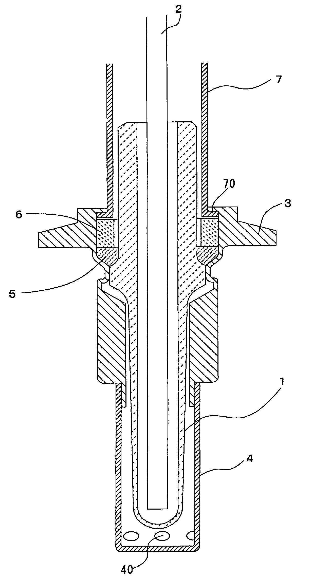
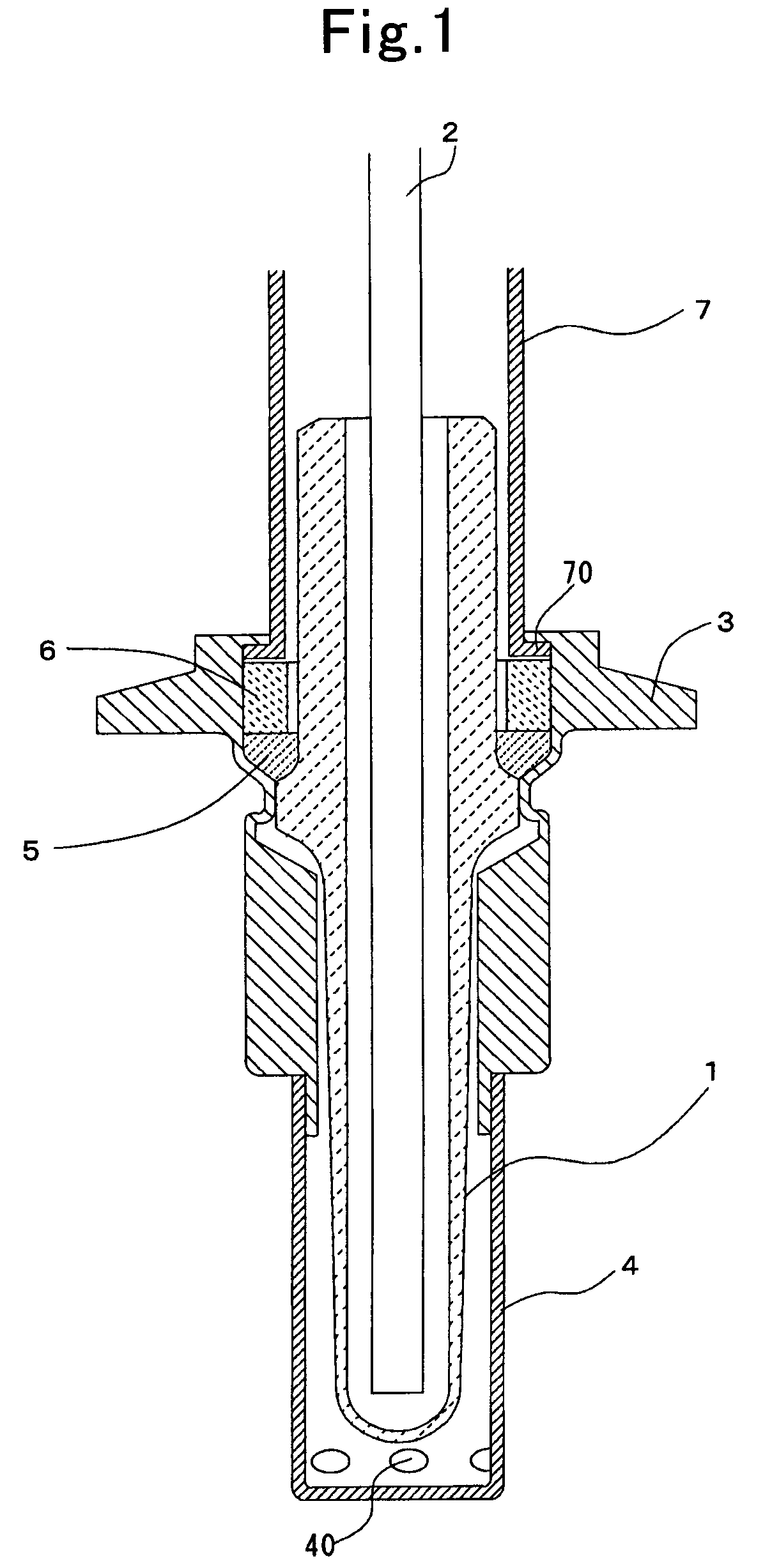
[0063]In FIG. 1, a cross-sectional diagram of a major part of an oxygen sensor that is directed to the present example is illustrated. This oxygen sensor is constituted of the following: a detector element 1 that is formed as a bottomed cylindrical shape and makes a test tube configuration; a heater 2 that is disposed inside the detector element 1, and which is formed as a rod shape and is made of ceramic; a casing 3 that accommodates the detector element 1 and heater 2 therein; a cylindrical protector 4 that is installed to the lower opposite end of the casing 3 and covers the bottom of the detector element 1 which projects from the lower opposite end of the casing 3; and a ring-shaped sealing portion 5 that is put in place in a gap between the outer circumferential surface of the detector element 1 and the inner circumferential surface of the casing 3; and additionally a spacer 6 that is made of cylinder-shaped ceramic; and an outer cylinder 7 that is fixed to the upp...


PUM

PropertyMeasurementUnit
porosityaaaaaaaaaa
particle diameteraaaaaaaaaa
temperatureaaaaaaaaaa

Abstract

A sealing portion is formed of a calcined body that is made by calcining a powder compact of a spherically-shaped granulated powder that is selected from the group consisting of alumina, aluminum titanate and cordierite. Anisotropy in physical properties is less likely to occur in the powder compact, because these ceramics are not only good in terms of thermal stability but also their spherically-shaped granulated powders are less likely to be oriented at the time of powder compacting. Therefore, the sealing portion comes to have a long longevity, because slippages between the particles are less likely to occur even when thermal histories are applied thereto, and because it can maintain the gas sealing property stably for a long period of time.

Description

[0001]This is a continuation of PCT application PCT / JP2009 / 055847 filed Mar. 24, 2009, which in turn is based on Japanese application No. 2008-99,378 filed Apr. 7, 2008, the entire contents of each of which is incorporated herein by reference.TECHNICAL FIELD[0002]The present invention relates to a gas sensor that detects an oxygen concentration and the like in exhaust gases, and to a process for manufacturing the same.BACKGROUND ART[0003]An oxygen sensor for detecting an oxygen concentration in exhaust gases has been installed to the exhaust system of automobile, and its signals have been used for the feedback control of air-fuel ratio, and the like. Moreover, they have also been used for the judgment on the degradation degree of catalyst for converting exhaust gases, and so forth.[0004]As for this oxygen sensor, those which employ a solid electrolyte such as zirconia have been used widely in recent years. In general, these solid electrolyte-type oxygen sensors are one that has a te...

Claims


Application Information

Patent Timeline
Patent Type & Authority Patents(United States)
IPC IPC(8): G01N27/407G01N27/417
CPCG01N27/407G01N27/4078
Inventor KAMIYA, SUMIOITO, TAKASHI
Owner TOYOTA JIDOSHA KK
Learn More