Phase and/or frequency detector, phase-locked loop and operation method for the phase-locked loop

Active Publication Date: 2013-06-11
UNITED MICROELECTRONICS CORP
View PDF35 Cites 3 Cited by
  • Summary
  • Abstract
  • Description
  • Claims
  • Application Information

AI Technical Summary

Benefits of technology

[0016]The present invention adds the delay circuit and the control circuit into the phase and/or frequency detector. Thus, the present invention can employ the delay circuit to prolong the rising period of each of the pulses of the signal outputted from the logic gate, so as to further prolong the rising period of each of the pulses of the frequency-increasing control signal (i.e., the signal outputted from the first flip-flop) and the rising period of each of the pulses of the frequency-reducing control signal (i.e., the signal outputted from the second flip-flop) outputted from the phase and/or frequency detector. Therefore, the problem of the dead zone of the conventional phase-locked loop can be solved, and the jittering problem of the o

Problems solved by technology

However, the phase-locked loop is prone to be interfered by noise, and this may cause the time offse

Method used


Image

  • Phase and/or frequency detector, phase-locked loop and operation method for the phase-locked loop
  • Phase and/or frequency detector, phase-locked loop and operation method for the phase-locked loop
  • Phase and/or frequency detector, phase-locked loop and operation method for the phase-locked loop

Examples


Example

[0036]The present invention will now be described more specifically with reference to the following embodiments. It is to be noted that the following descriptions of preferred embodiments of this invention are presented herein for purpose of illustration and description only. It is not intended to be exhaustive or to be limited to the precise form disclosed.

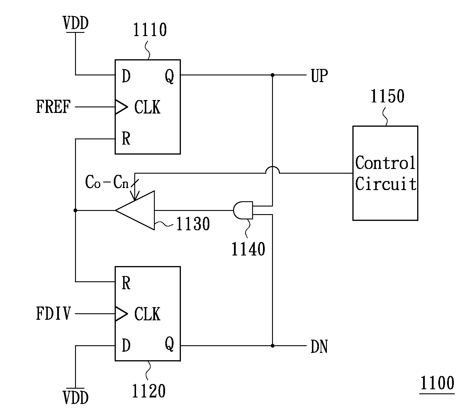
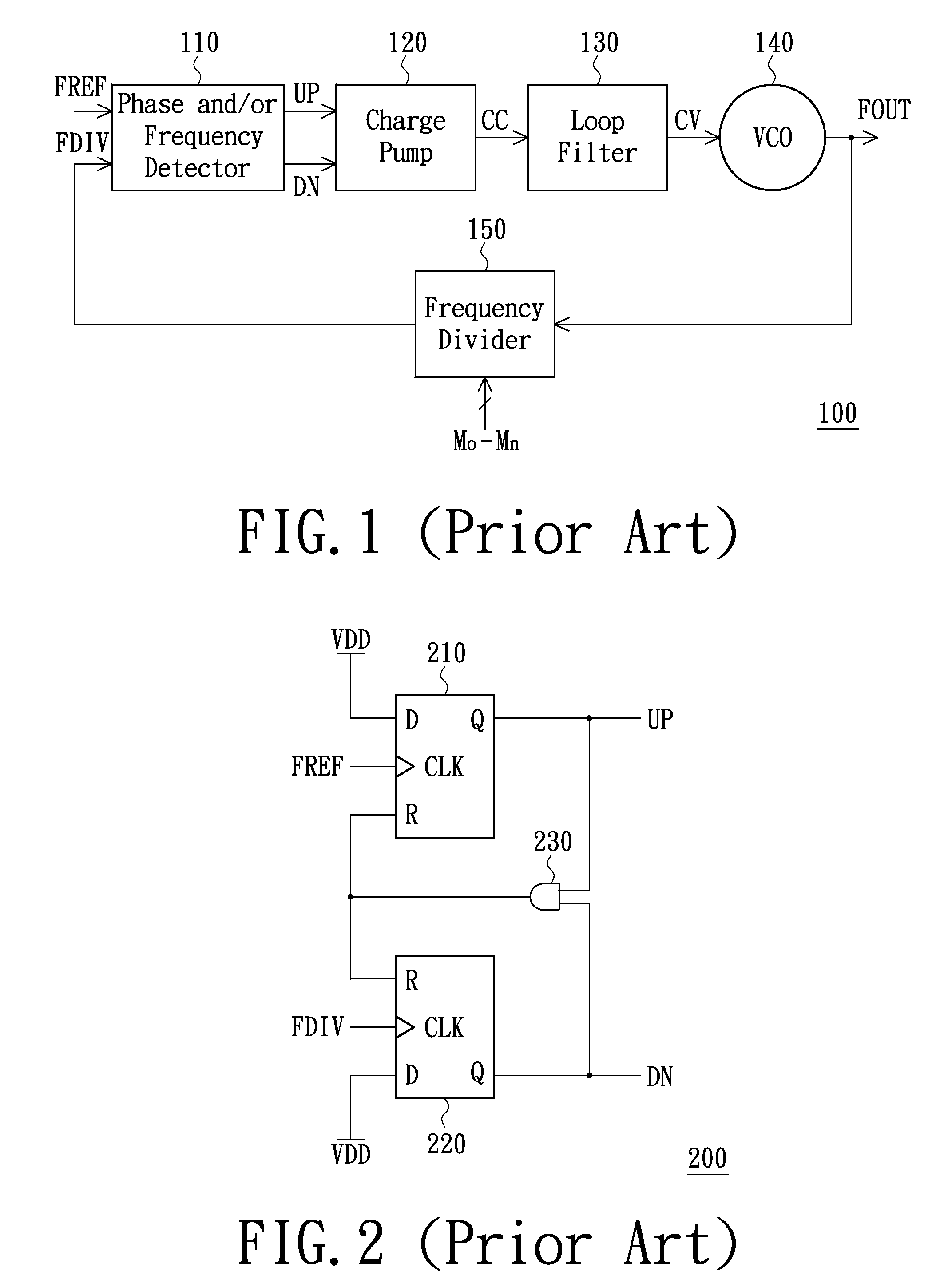
[0037]FIG. 1 is a block view of a phase-locked loop (PLL). As shown in FIG. 1, the phase-locked loop 100 comprises a phase and / or frequency detector 110, a charge pump 120, a loop filter 130, a voltage-controlled oscillator (VCO) 140 and a frequency divider 150. The phase and / or frequency detector 110 is configured for receiving a frequency-divided signal FDIV and a reference signal FREF with a reference frequency, and the phase and / or frequency detector 110 determines whether to output a frequency-increasing control signal UP and a frequency-reducing control signal DN according to the phase difference between the frequency-divid...


PUM


Abstract

The present invention provides a phase and/or frequency detector, a PLL and an operation method for the PLL. The phase and/or frequency detector comprises two flip-flops, a logic gate, a control circuit and a delay circuit. The clock-input terminals of the two flip-flops receive a reference signal and a frequency-divided signal respectively. The logic gate receives signals outputted from the data-output terminals of the two flip-flops. The control circuit is configured for generating a corresponding delay control signal according to an oscillating frequency of an oscillating signal outputted from the PLL. The delay circuit is configured for altering a prolonged period according to the delay control signal to output a reset signal to the reset terminals of the two flip-flops.

Description

FIELD OF THE INVENTION[0001]The present invention relates to the technology of the phase-locked loop (PLL), and more particularly to a phase and / or frequency detector which can be used to solve the jittering problem of the output signal of the conventional phase-locked loop, a phase-locked loop adopting the above phase and / or frequency detector, and an operation method for the above phase-locked loop.BACKGROUND OF THE INVENTION[0002]Phase-locked loop (PLL) is an auto-controlling circuit system, which is able to track the frequency and the phase of an input signal. The phase-locked loop tracks and locks the phases and the frequencies of an output signal and the input signal, so as to keep the phase and the frequency of the output signal at a predetermined value or in a predetermined range. Currently, the phase-locked loop has been widely used in computers and consumer products.[0003]However, the phase-locked loop is prone to be interfered by noise, and this may cause the time offset ...

Claims


Application Information

Patent Timeline
IPC IPC(8): H03L7/06
CPCH03L7/089H03L7/0891
Inventor CHEN, CHIEN-LIANG
Owner UNITED MICROELECTRONICS CORP
Why Eureka
Try Eureka