Variable pitch propeller

a variable-pitch propeller and variable-pitch technology, which is applied in the direction of rotors, marine propulsion, vessel construction, etc., can solve the problems of prone to inaccurate mechanisms, reduced top speed, and reduced efficiency of fixed-pitch propellers at lower vehicle speeds, and achieves fine pitch control. , the effect of simple structur

Active Publication Date: 2013-06-18
BRP US
View PDF26 Cites 13 Cited by
  • Summary
  • Abstract
  • Description
  • Claims
  • Application Information

AI Technical Summary

Benefits of technology

[0010]It is a further object of the present invention to provide a variable pitch propeller having a simple construction.
[0011]It is a further object of the present invention to provide a variable pitch propeller capable of varying a pitch angle at different rates.
[0012]It is a further object of the invention to provide a variable pitch propeller capable of fine pitch control when the propeller provides thrust in the forward direction, and rapid change of pitch to provide thrust in the reverse direction.
[0013]It is a further object of the invention to provide a method of varying the pitch of a propeller blade that provides thrust in the forward direction, and rapid change of pitch to provide thrust in the reverse direction.

Problems solved by technology

The fixed pitch is typically at an angle that provides maximum efficiency at normal cruising speeds, however fixed pitch propellers typically have reduced efficiency at lower vehicle speeds.
Alternatively, the pitch of a propeller can be fixed at an angle that provides better acceleration or pulling capacity at lower speeds, which typically results in a reduced top speed.
As a result, fixed pitch propellers typically are a compromise between good acceleration, a higher top speed and fuel consumption.
Variable pitch propellers allow for increased efficiency at both low and high speeds, but they are subject to a number of design concerns.
These mechanisms are prone to being inaccurate and do not allow fine adjustment control over the blade pitch.
In addition, these mechanisms generally do not allow sufficient pitch variation for the propeller to propel the watercraft in a reverse direction.
In addition, variable pitch propeller assemblies must operate within a limited range of size and weight, particularly if it is also desired to vent engine exhaust through the propeller assembly, imposing limits on the size of the actuator and its freedom of movement, thereby imposing a trade-off between finer pitch control and a wider range of available pitch angles.
This transmission adds size and weight to the gear case, resulting in increased drag and fuel consumption.

Method used


Image

  • Variable pitch propeller
  • Variable pitch propeller
  • Variable pitch propeller

Examples


Embodiment Construction

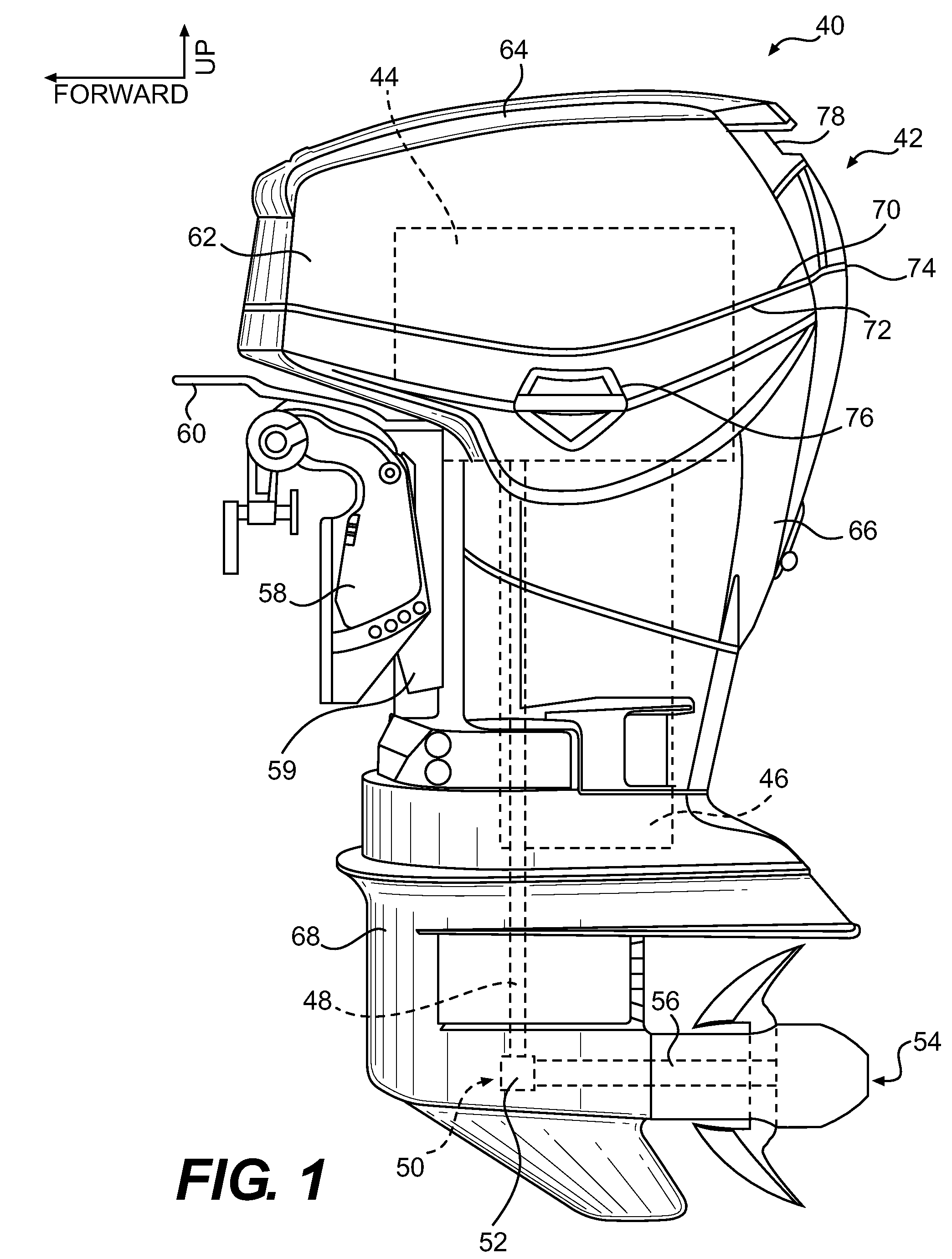
[0056]Referring to FIG. 1, a marine outboard engine 40 will be described according to the present invention. It should be understood that the present invention is applicable to other marine applications involving propellers, such as inboard engines and stern drives.

[0057]FIG. 1 is a side view of a marine outboard engine 40 having a cowling 42. The cowling 42 surrounds and protects an engine 44, shown schematically. The engine 44 may be any suitable engine known in the art, such as an internal combustion engine. An exhaust system 46, shown schematically, is connected to the engine 44 and is also surrounded by the cowling 42.

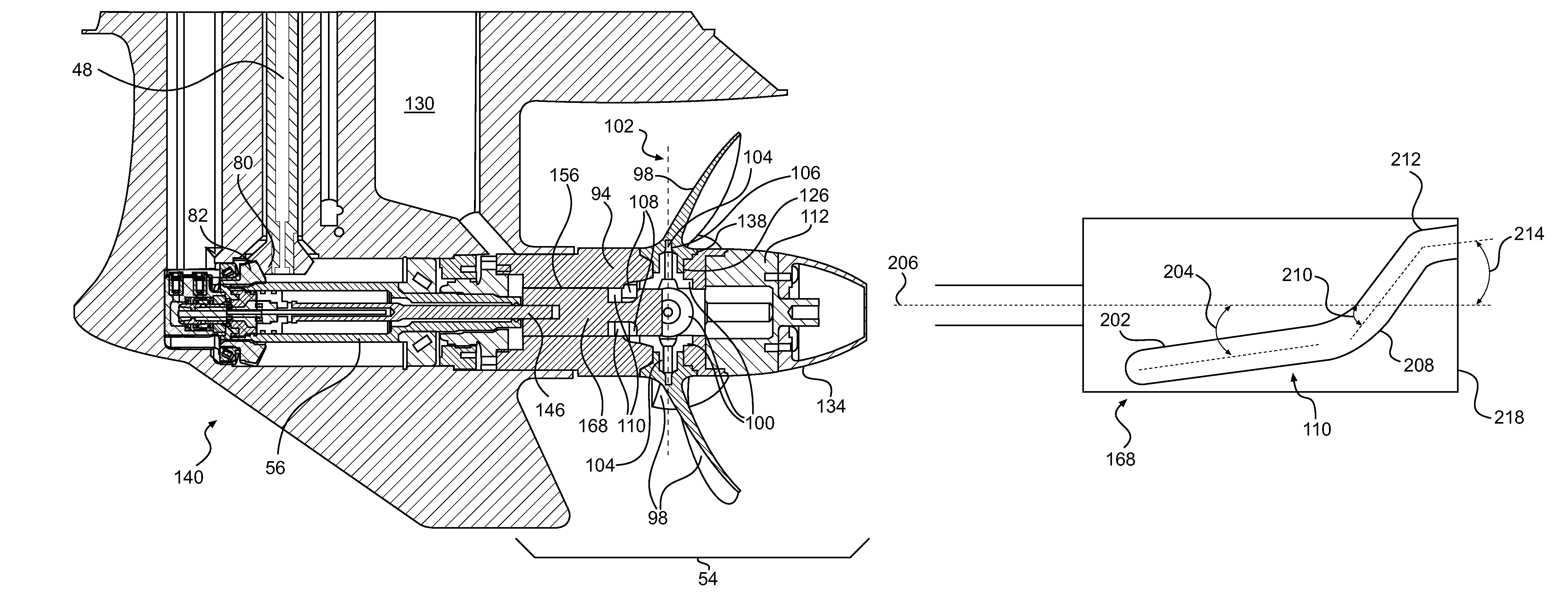
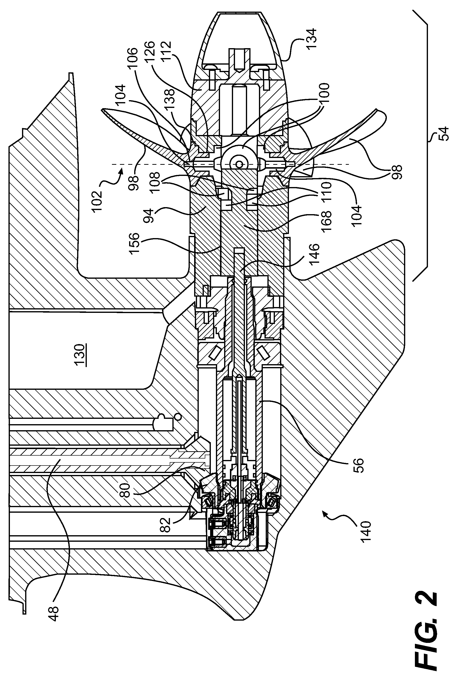
[0058]The engine 44 is coupled to a vertically oriented driveshaft 48. The driveshaft 48 is coupled to a drive mechanism 50, which includes a transmission 52 and a bladed rotor, such as a propeller assembly 54 (shown schematically) mounted on a propeller shaft 56. The propeller shaft 56 is generally perpendicular to the driveshaft 48. The drive mechanism 50, the p...


PUM


Abstract

A propeller assembly is disclosed, comprising propeller blades pivotably mounted on a propeller hub. A cam follower is disposed on each propeller blade. A cam is movable between a first position, a second position and a third position. Recesses formed in the cam have a first segment, a second segment and a third segment, oriented at first, second and third angles. The first segment is oriented at a first angle relative to the central axis. The cam followers engage the first segment of the recesses when the cam moves between first and second positions to vary the pitch of the propeller blades between a first pitch and a second pitch. The cam followers engage the second segment of the recesses when the cam moves between second and third positions to vary the pitch of the propeller blades between the second pitch and a third pitch.

Description

CROSS-REFERENCE[0001]The present application claims priority to U.S. Provisional Patent Application No. 61 / 110,094 filed on Oct. 31, 2008, the entirety of which is incorporated herein by reference.FIELD OF THE INVENTION[0002]The present invention relates to a variable pitch propeller, specifically for marine applications.BACKGROUND OF THE INVENTION[0003]Many boats and other watercraft are propelled by one or more inboard or outboard engines or a stern drive system, which drives one or more propellers. Each propeller typically has three or four blades, but may have as few as two or as many as five or six. The base of each blade is mounted at an angle, or pitch, relative to a radial plane transverse to the axis of rotation of the propeller shaft. Propellers may be constructed with blades having a fixed pitch. The fixed pitch is typically at an angle that provides maximum efficiency at normal cruising speeds, however fixed pitch propellers typically have reduced efficiency at lower veh...

Claims


Application Information

Patent Timeline
Patent Type & Authority Patents(United States)
IPC IPC(8): B63H3/04
CPCB63H3/008
Inventor NOBLE, MARK C.MCCHESNEY, RICHARDTATGE, LAVERNECALAMIA, DAVEEWENS, GERALDWENDLER, RUDOLFPFIFFNER, SIMON
Owner BRP US
Why Eureka
Try Eureka