Calibration method of UV sensor for UV curing

a technology of uv sensor and calibration method, which is applied in the direction of optical radiation measurement, instruments, semiconductor/solid-state device testing/measurement, etc., can solve the problems of reducing the accuracy of calibration, so as to reduce the exposure and eliminate environmental or external calibration errors , the effect of high accuracy

Active Publication Date: 2013-06-18
ASM JAPAN
View PDF7 Cites 372 Cited by
  • Summary
  • Abstract
  • Description
  • Claims
  • Application Information

AI Technical Summary

Benefits of technology

[0009]Consequently, in an aspect, an object of the present invention is to provide an in-situ calibration method of a UV feedback sensor (built-in UV sensor) which gives feedback to a UV power control system, wherein another UV sensor for calibration is provided inside a UV unit. The another UV sensor is exposed to UV light substantially less frequently than is the built-in UV sensor, and thus, the another UV sensor is not subject to substantial degradation and can calibrate the built-in UV sensor. In some embodiments, the another UV sensor is equipped with a shutter which is closed (i.e., blocking a UV receiving unit of the another UV sensor from UV light) when the another UV sensor is not measuring illuminance and which opens to measure illuminance. In some embodiments, the another UV sensor is exposed to UV light only when measuring illuminance for calibration of the built-in UV sensor. Since degradation of the another UV sensor is negligible or insubstantial due to the substantially less exposure to UV light as compared with the built-in UV sensor, and also since the another UV sensor is positioned in a vicinity of the built-in UV sensor inside the UV unit and can measure illuminance simultaneously with the built-in UV sensor, environmental or external errors of calibration can be eliminated, and calibration can be conducted highly accurately. Further, since the in-situ calibration can eliminate external calibration such as those using a measuring jig, and since the in-situ calibration can be conducted during UV treatment of a substrate, productivity can significantly be improved. Additionally, the in-situ calibration can easily be automated by following a predetermined sequence, thereby further improving productivity.

Problems solved by technology

However, the built-in UV sensor is subject to degradation with time due to exposure to UV light, and as a result, illuminance measured by the built-in UV sensor is shifted.
However, the built-in UV sensor is also subject to degradation with time.
However, since the above calibration is conducted under different environments, and also since the exterior UV sensor is provided in the measuring jig, the illuminance measured by the exterior UV sensor may not accurately represent the ideal illuminance measured by the built-in UV sensor.
Further, such external calibration lowers productivity.

Method used


Image

  • Calibration method of UV sensor for UV curing
  • Calibration method of UV sensor for UV curing
  • Calibration method of UV sensor for UV curing

Examples


example 1

Illuminance Retention Ratio of UV Feedback Sensor and UV Calibration Sensor

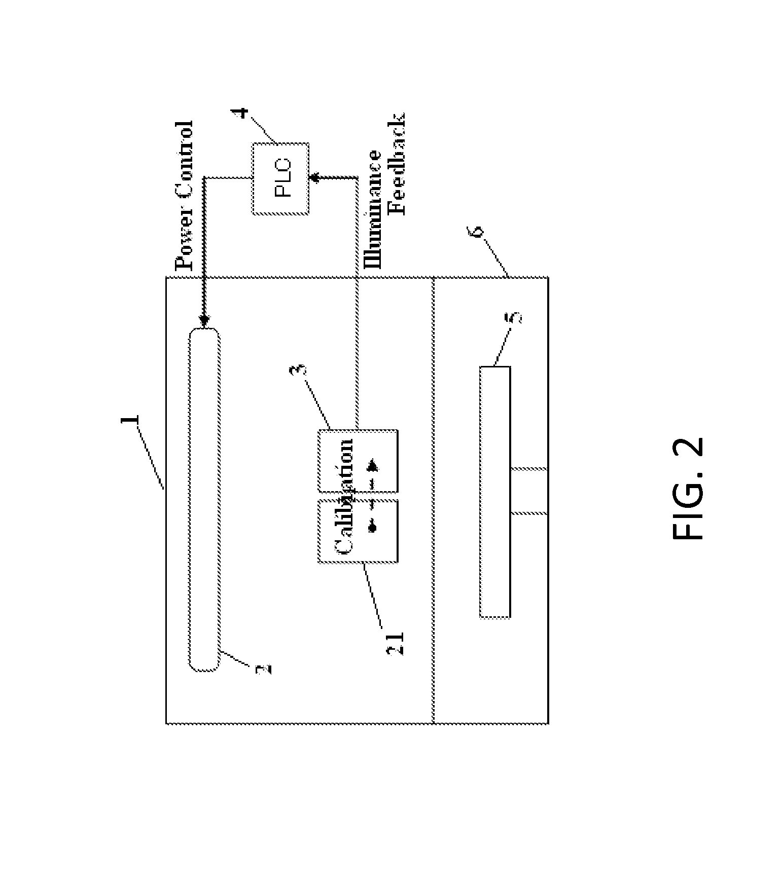
[0055]An apparatus shown in FIG. 2 was used, wherein the UV lamp was a mercury lamp. A UV feedback sensor and a UV calibration sensor were of the same type for measuring light having a wavelength of 365 nm. Both the sensors were provided with shutters which were capable of opening for monitoring illuminance. The UV lamp was turned on by inputting 60% of full power for 120 seconds, and then 100% of full power for 600 seconds. This cycle of 60% and 100% constituted one cycle, and the UV lamp continuously emitted UV light by repeating the cycle for this experiment wherein no substrate was placed on a heater. By using a pulse of 60% of full power, overheating the apparatus was avoided.

[0056]The illuminance from the UV lamp changed over time due to deterioration of the UV lamp itself. First, in order to determine deterioration of the UV lamp, illuminance was measured using the UV calibration sensor which was expos...

example 2

Operation Rate of Using UV Feedback Sensor and UV Calibration Sensor

[0064]The same system as in Example 1 was used, and the shutter of the UV feedback sensor opened every 10 hours, whereas the shutter of the UV calibration sensor opened every 100 hours. No external calibration was conducted. The time used for this in-situ calibration was considered as downtime, and the operation rate was determined. The operation rate was defined as a ratio of (T-D) / T per month (F: total operation time of the UV lamp, D: downtime).

[0065]In comparison, the same system as in Example 1 and an external UV sensor of the same type were used. The shutter of the UV feedback sensor opened every 10 hours, whereas the shutter of the UV calibration sensor remained closed. External calibration was conducted every 100 hours, 200 hours, and 300 hours, using the external UV sensor. The time used for this external calibration was considered as downtime, and the operation rate was determined.

[0066]The results are sho...


PUM


Abstract

A method for managing UV irradiation for treating substrates in the course of treating multiple substrates consecutively with UV light, includes: exposing a first UV sensor to the UV light at first intervals to measure illumination intensity of the UV light so as to adjust the illumination intensity to a desired level based on the measured illumination intensity; and exposing a second UV sensor to the UV light at second intervals to measure illumination intensity of the UV light so as to calibrate the first UV sensor by equalizing the illumination intensity measured by the first UV sensor substantially with the illumination intensity measured by the second UV sensor, wherein each second interval is longer than each first interval.

Description

BACKGROUND[0001]1. Field of the Invention[0002]The present invention generally relates to a method for calibrating a UV sensor and a method for controlling UV irradiation for curing a semiconductor substrate using the calibration method.[0003]2. Description of the Related Art[0004]Conventionally, UV irradiation apparatuses have been commonly used for the modification of various processing targets with UV light and the production of substances by means of photochemical reaction. The recent trend of higher integration of devices results in increasingly finer wiring designs and multi-layer wiring structures, which gives rise to a need to reduce the interlayer volume in order to increase the device speed while reducing the power consumption. One method of reducing the interlayer volume is to cure a low-k material through UV irradiation and thereby increase its mechanical strength (for example, U.S. Pat. No. 6,759,098 and U.S. Pat. No. 6,296,909).[0005]In the UV irradiation apparatuses, ...

Claims


Application Information

Patent Timeline
Patent Type & Authority Patents(United States)
IPC IPC(8): G01D18/00G01R31/26
CPCG01J1/429H01L21/26H01L21/324
Inventor ARAI, HIROFUMI
Owner ASM JAPAN
Why Eureka
Try Eureka