

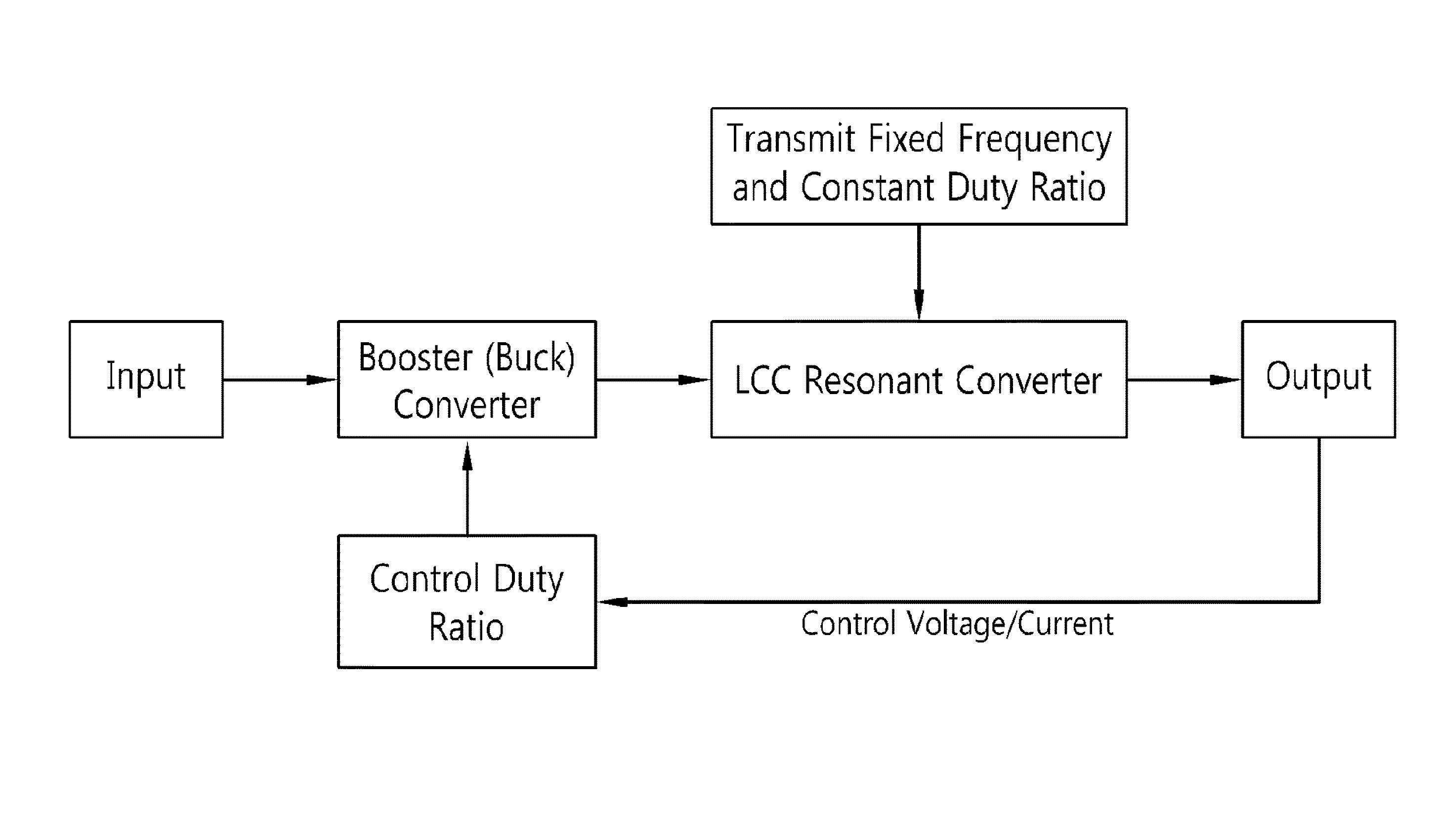
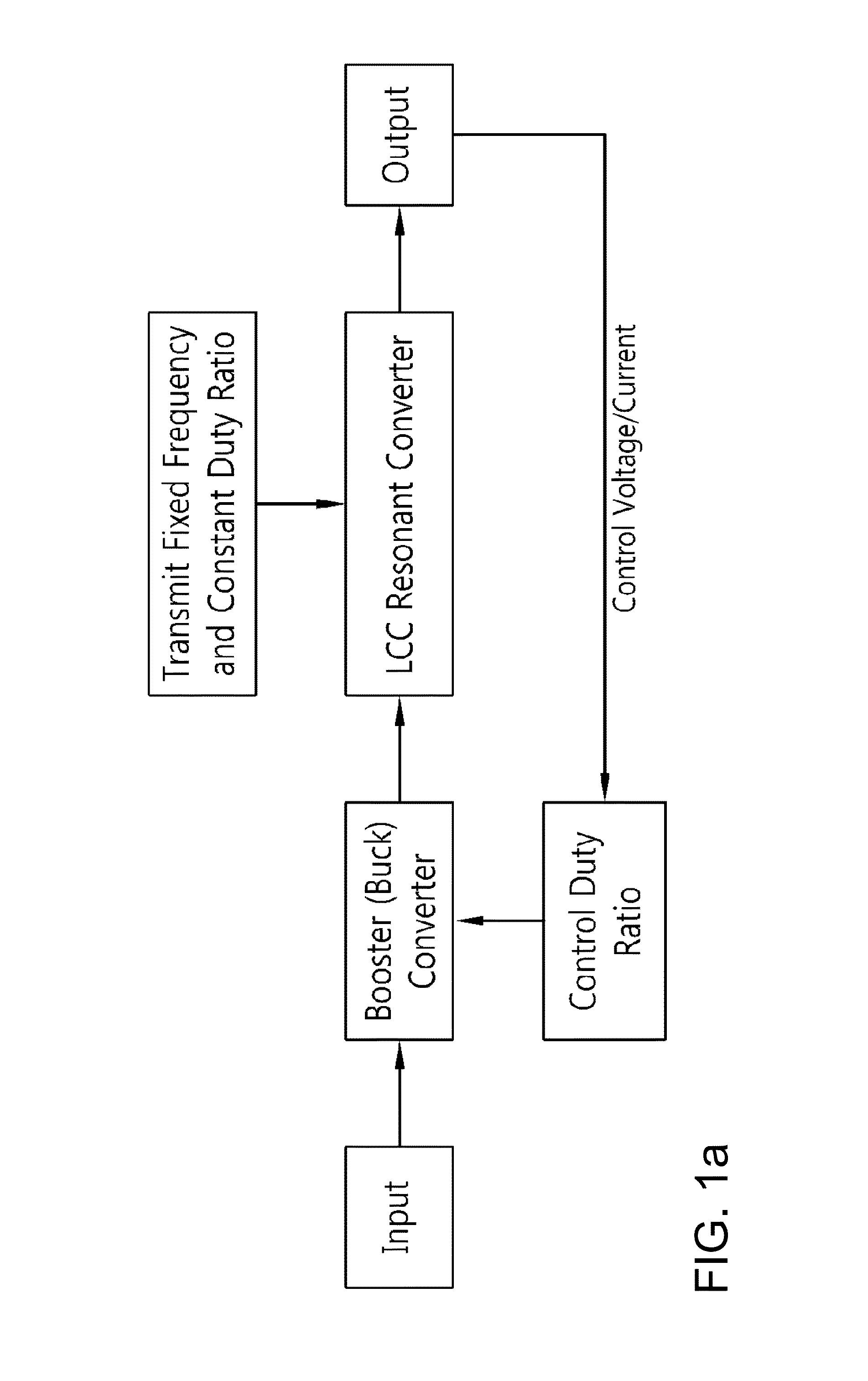
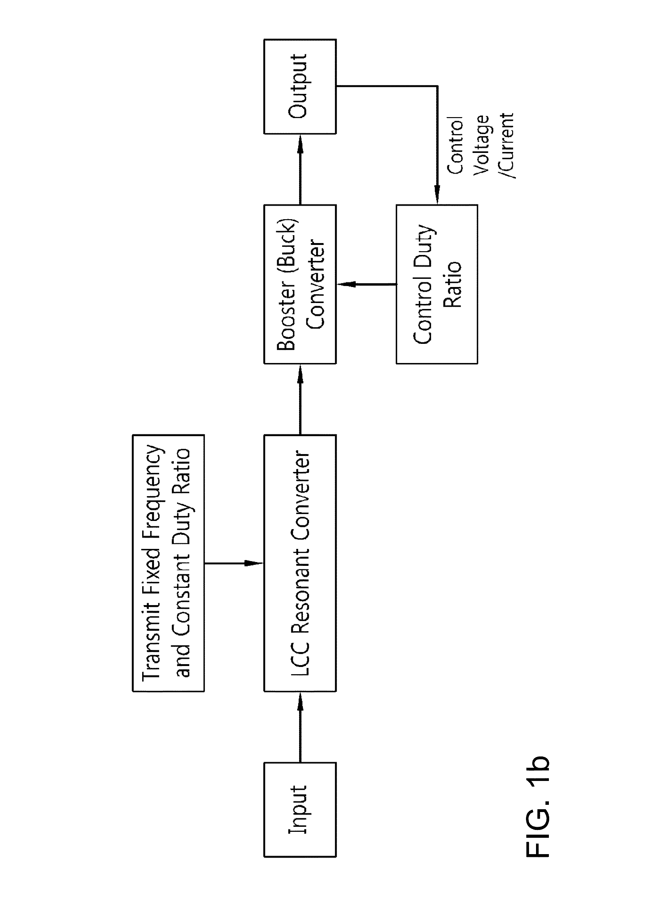
Two-stage insulated bidirectional DC/DC power converter using a constant duty ratio LLC resonant converter
a llc resonant converter and bidirectional dc/dc technology, applied in the direction of electric variable regulation, process and machine control, instruments, etc., can solve the problems of reducing system efficiency, comparatively high cost of control integrated circuits, etc., and achieves stable energy transfer, reduced efficiency, and reduced complexity of output control
- Summary
- Abstract
- Description
- Claims
- Application Information
AI Technical Summary
Benefits of technology
Problems solved by technology
Method used
Image

Examples
application example 1
[0039]FIGS. 3(a) and 3(b) are circuit diagrams of the high-efficiency bidirectional DC / DC power converter using an unregulated bus converter according to a preferred embodiment of the present invention.
[0040]As illustrated in FIGS. 3(a) and 3(b), the high-efficiency bidirectional DC / DC power converter using an unregulated bus converter according to an embodiment of the invention comprises a controlled DC / DC converter and an unregulated bus converter.
[0041]The controlled DC / DC converter is for smoothing the external output according to an embodiment of the invention, and to this end, receives feedback from the external output.
[0042]The unregulated bus converter only provides the functions of insulation between input and output of the LLC resonant converter and of a fixed step-up rate (or fixed step-down rate in reverse operation) according to the turn ratio of the transformer, and therefore, does not require control.
[0043]More specifically, FIGS. 3(a) and 3(b) are circuit diagrams of...
application example 2
[0085]Next, an explanation will be provided on the high-efficiency DC / DC power converter using an unregulated bus converter according to an embodiment of the invention, with reference to FIGS. 4(a) and 4(b). In the description below, parts that overlap with the explanation provided above in Application Example 1 on the high-efficiency DC / DC power converter using an unregulated bus converter according to an embodiment of the invention will be omitted or abbreviated.
[0086]FIGS. 4(a) and 4(b) are circuit diagrams of the high-efficiency bidirectional DC / DC power converter using an unregulated bus converter according to a preferred embodiment of the present invention.
[0087]A high-efficiency DC / DC power converter using an unregulated bus converter according to Application Example 2, when operated in the forward direction, as illustrated in FIG. 4(a), comprises a booster converter 100 and an LLC resonant converter 200. It further comprises: an output voltage detector circuit 300, configure...
application example 3
[0100]FIGS. 5(a) and 5(b) are circuit diagrams of the high-efficiency bidirectional DC / DC power converter using an unregulated bus converter according to a preferred embodiment of the present invention. It is an application example wherein the first resonant switches (Sp1, Sp4) and the second resonant switches (Sp2, Sp3) on the primary side are in pairs, consisting of four switches in total.
[0101]According to an embodiment of the present invention, the high-efficiency DC / DC power converter using an unregulated bus converter, when the operation is in the forward direction, as illustrated in FIG. 5(a), comprises: a boost converter 100; and an LLC resonant converter 200. Also, it further comprises: an output voltage detector circuit 300, configured to detect the output voltage of the LLC resonant converter 200; a bidirectional converter control unit 110, configured to control the boost converter 100 by the output voltage detector circuit 300; and a constant duty ratio gate pulse genera...
PUM
 Abstract
Description
Claims
Application Information