Illumination device comprising a collimator

a collimator and collimator technology, which is applied in the direction of lighting and heating apparatus, planar/plate-like light guides, instruments, etc., can solve the problems of affecting the affecting the effect of the collimator, and reducing the thickness of the collimator, so as to achieve the effect of slim appearance of the system, easy integration with the surrounding environment, and elegant appearan

Active Publication Date: 2013-07-02
SIGNIFY HLDG BV
View PDF32 Cites 51 Cited by
  • Summary
  • Abstract
  • Description
  • Claims
  • Application Information

AI Technical Summary

Benefits of technology

[0007]Hence, a problem is how to manipulate the light distribution in all directions without substantially varying the thickness of the light guide (or “collimator” or “waveguide”). The advantage of a system of substantially constant thickness is that it allows for elegant, thin luminaire designs that are relatively easy to manufacture, and which may relatively easily be installed as furniture (or furniture element) or implemented in furniture. Therefore, there is a desire to provide an alternative flat illumination device based on a light guide, and to further improve the beam shape of such flat light guides. Hence, it is an aspect of the invention to provide an alternative illumination device, which preferably further at least partially obviates one or more of above-described drawbacks, and which preferably provides a collimated beam or a more collimated beam.
[0009]It surprisingly appears that such device may provide a beam with advantageous beam shape, which may be well collimated in both longitudinal and latitude direction: such illumination device may be relatively flat, but nevertheless have a collimation in the plane of the waveguide or collimator as well perpendicular to the waveguide. It appears that this collimation may be obtained by introducing grooves in the one or more of the top collimator surface (also indicated herein as “top surface”), the bottom collimator surface (also indicated herein as “bottom surface”), the first collimating side edge (also herein indicated as “first side edge”) and the second collimating side edge (also herein indicated as “second side edge”), and thus without substantially further introducing widening or narrowing features. Hence, in this way a flat collimator may be provided, having collimation in both directions.
[0017]In a preferred embodiment, the plurality of (these) grooves may virtually converge at a position coinciding with the light source. Here the phrase “position coinciding with the light source” indicates the position of the light source where the light source emits light (i.e. its light emitting part (like the light emitting surface of an LED, the discharge of a discharge source, or the filament of a incandescent type of lamp). Note that the illumination device may have a light source that can be considered in approximation as a point source, but may also have a line source (such as a luminescent tube; TL), which may then especially be arranged substantially perpendicular to the top collimator surface and / or the bottom collimator surface. When the plurality of grooves virtually converge at a position coinciding with the light source, the best collimation may be obtained. However, the plurality of grooves may virtually converge at a position upstream of the light source, for instance within about 0-100 cm, like about 0-10 cm. In fact, the plurality of grooves may virtually converge at a position infinitely upstream of the light source: hence, in an embodiment, the plurality of grooves are arranged substantially parallel. Even then, even better collimation is obtained than without the (plurality) of grooves. Choosing the convergence allows controlling the collimation. The amount of latitudinal collimation may be a measure of the effectiveness of the grooves. When the convergence point lies more upstream, the latitudinal collimation may relatively be worse, but the longitudinal collimation relatively becomes better.
[0031]The combination of a light source and the collimator (the lighting unit) can be used per se as illumination device, but may also be integrated in a larger entity, especially a plate. Hence, in a further aspect, the invention provides an embodiment of the illumination device, comprising a substantially flat plate comprising the lighting unit, the plate having a top plate surface, a bottom plate surface, and an plate edge, wherein the top collimator surface coincides with at least part of the top plate surface or at least part of the bottom plate surface and wherein the bottom collimator surface coincides with at least part of the bottom plate surface or at least part of the top plate surface. An advantage of such a construction is that such an illumination device may (more easily) be used as furniture or incorporated in furniture (as furniture element). Another advantage is that such plate may comprise a plurality of collimators. In principle, one light source may serve more than one collimator. However, preferably, each collimator has its “own” light source. Note that the term “light source” may also include a plurality of light sources. Therefore, in a specific embodiment, the illumination device comprises (a plate comprising) a plurality of lighting units.

Problems solved by technology

A thickness increase (as in the case of a collimator) is in general however unwanted, since it may deteriorate the slim appearance of the system.
On the other hand, a wedge-like thickness-decrease may complicate manufacturability (in particular the thin edge), and generally may need additional light directing optics that add thickness.
Hence, a problem is how to manipulate the light distribution in all directions without substantially varying the thickness of the light guide (or “collimator” or “waveguide”).

Method used


Image

  • Illumination device comprising a collimator
  • Illumination device comprising a collimator
  • Illumination device comprising a collimator

Examples


Embodiment Construction

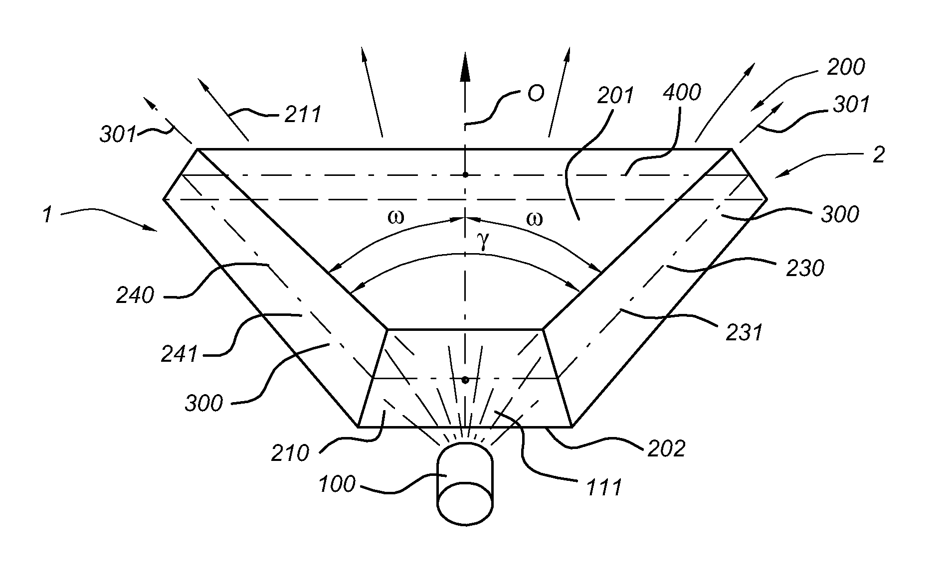
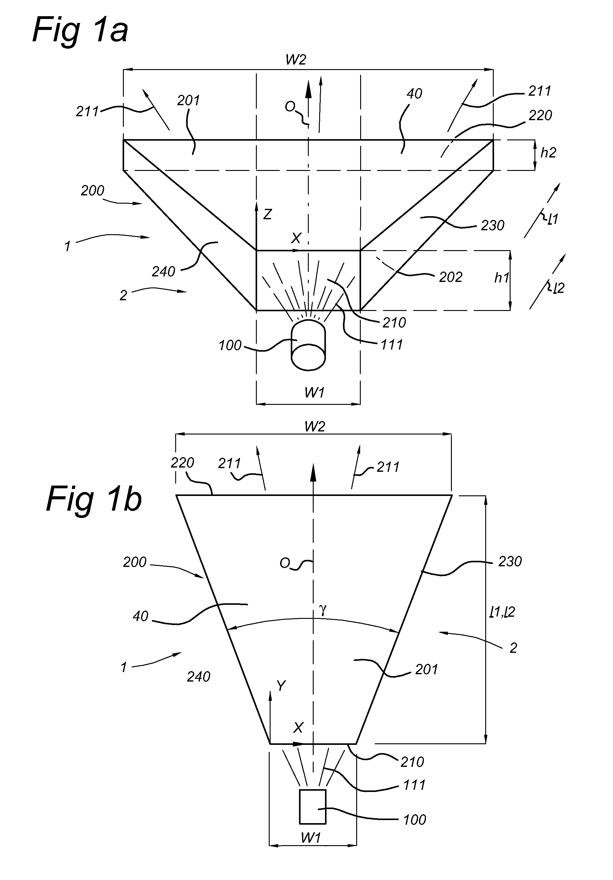
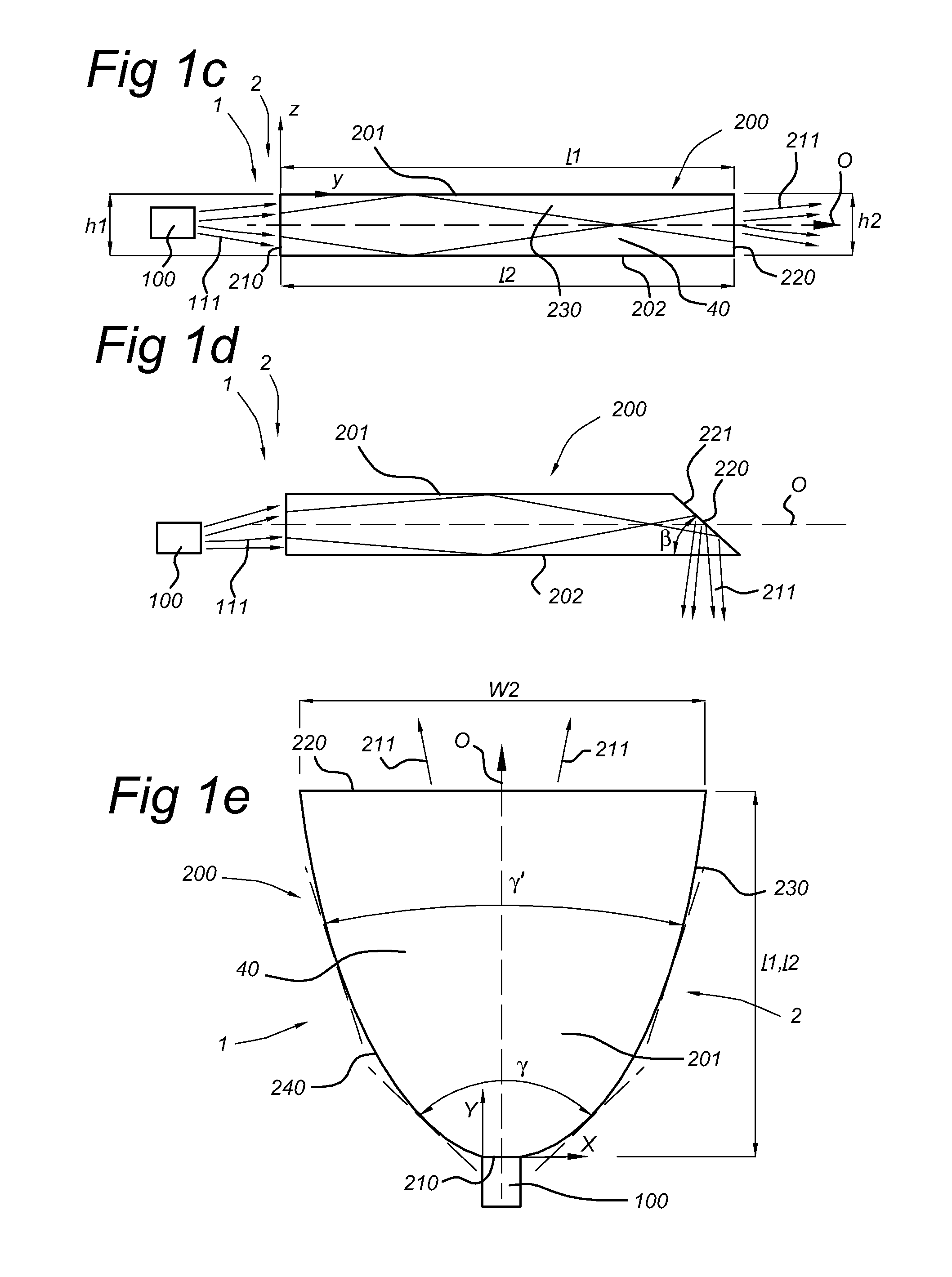
[0048]FIGS. 1a-1c schematically depicts an illumination device 1 arranged to generate device light 211. The illumination device 1 comprising a lighting unit, indicated with reference 2. The lighting unit 2, comprises a light source 100, arranged to generate light source light 111, and a substantially flat collimator 200, arranged to collimate the light source light 111 and provide the device light 211.

[0049]The light source 100 may be any light source, but may especially be a LED (including a plurality of LEDs).

[0050]The collimator 200 is a waveguide, which may be solid or hollow. Herein, it is further referred to solid waveguides, which are indicated with reference 40. The collimator 200 has an entrance window 210 and an edge window 220, a top collimator surface 201 (“top surface”) and a bottom collimator surface 202 (“bottom surface”), which are preferably arranged substantially parallel, a first collimating side edge 230 (“first side edge”) and a second collimating side edge (240...


PUM


Abstract

The invention provides an illumination device (1) comprising a lighting unit (2). The lighting unit (2) comprises a light source (100) and a substantially flat collimator (200), arranged to collimate light source light (111). The collimator (200) has an entrance window (210), an edge window (220), a top collimator surface (201), a bottom collimator surface (202), a first collimating side edge (230) and a second collimating side edge (240). The lighting unit has an optical axis (O). One or more of the top collimator surface (201), the bottom collimator surface (202), the first collimating side edge (230) and the second collimating side edge (240) comprise n*½ grooves (300), wherein n is a positive integer number, and wherein the grooves (300) independently have a longitudinal axis (301) having a groove direction angle (ω) with the optical axis (O) ≧0° and & and <90°.

Description

FIELD OF THE INVENTION[0001]The invention relates to an illumination device comprising a collimator, and especially to such illumination device for use as or in furniture.BACKGROUND OF THE INVENTION[0002]Relatively flat illumination devices are known in the art and are for instance described in U.S. Pat. No. 7,025,482 and U.S. Pat. No. 7,181,378.[0003]U.S. Pat. No. 7,025,482 describes a light guide member and an illuminating device which are able to efficiently uniformly irradiate illumination light to only an area requiring illumination. Therefore, a reflection face is constructed by reflection stripes such as many grooves, etc. widened in a concentric circle shape. Light from a light source unit is widened toward this entire reflection face without irregularities by a diffusing portion such as a reflection prism, etc. Thus, only the range actually requiring the illumination can be illuminated without irregularities, and visibility of the illumination range using a front light is r...

Claims


Application Information

Patent Timeline
Patent Type & Authority Patents(United States)
IPC IPC(8): F21V5/00F21Y101/00
CPCG02B6/0011G02B6/0078G02B6/0045
Inventor VISSENBERG, MICHEL CORNELIS JOSEPHUS MARIEBERGMAN, ANTHONIE HENDRIKDEKKER, TIMCENNINI, GIOVANNI
Owner SIGNIFY HLDG BV
Why Eureka
Try Eureka