Numerical control device for tool machine

a technology of numerical control and tool machine, which is applied in the direction of program control, electric controller, electric programme control, etc., can solve the problems of phase error between the movement directions, machining error, and thereby reducing the accuracy of work machining

Inactive Publication Date: 2013-07-02
SHINNIPPON KOKI
View PDF12 Cites 4 Cited by
  • Summary
  • Abstract
  • Description
  • Claims
  • Application Information

AI Technical Summary

Benefits of technology

[0010]It is an object of the present invention to provide a numerical control device for a tool machine that can resolve the above-described problems.
[0011]It is an object of the present invention to provide a numerical control device for a tool machine that can increase the work machining accuracy in the case in which the movement directions of a work and a tool include different movement directions.

Problems solved by technology

However, the problem associated with typical tool machines, inclusive of such a turning device, is that when the movement directions of a work and a tool include different movement directions, a machining error occurs and the work machining accuracy is thereby decreased.
One of the factors causing the machining error is a phase error between movement directions occurring when the work and the tool are moved in a plurality of mutually different directions at mutually different acceleration-deceleration time constants.
This is because setting different acceleration-deceleration time constants in different movement directions causes a difference in a time interval required for acceleration and deceleration between the movement directions, thereby creating a phase error between the movement directions.
Another factor causing the machining error is the so-called inner rotation error of the work and tool.
This inner rotation error is an error of the actual movement pass of the work and tool with respect to the movement command pass of the work and tool occurring due to such a phenomenon.
However, a delay occurs in the movement positions of the work and tool following the secondary distribution pulses with respect to the movement positions of the work and tool following the movement command, this delay corresponding to the degree of relaxation of variations (acceleration-deceleration) in the movement speeds of the work and tool caused by the secondary distribution.
As a result, the work and tool start moving in the changed movement direction before the work and tool reach the predetermined position and therefore the aforementioned inner rotation error occurs.

Method used


Image

  • Numerical control device for tool machine
  • Numerical control device for tool machine
  • Numerical control device for tool machine

Examples


first embodiment

[0037](First Embodiment)

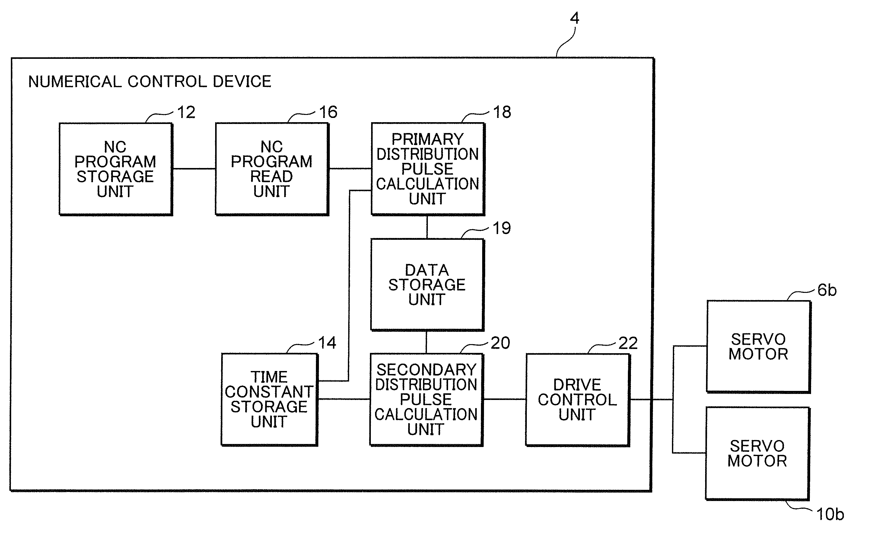
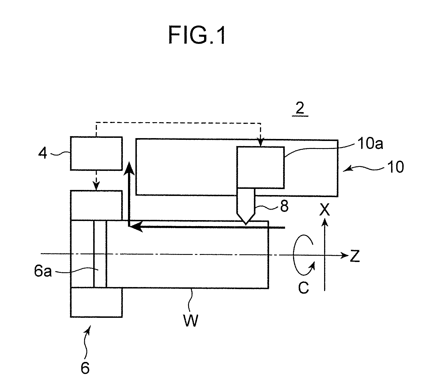
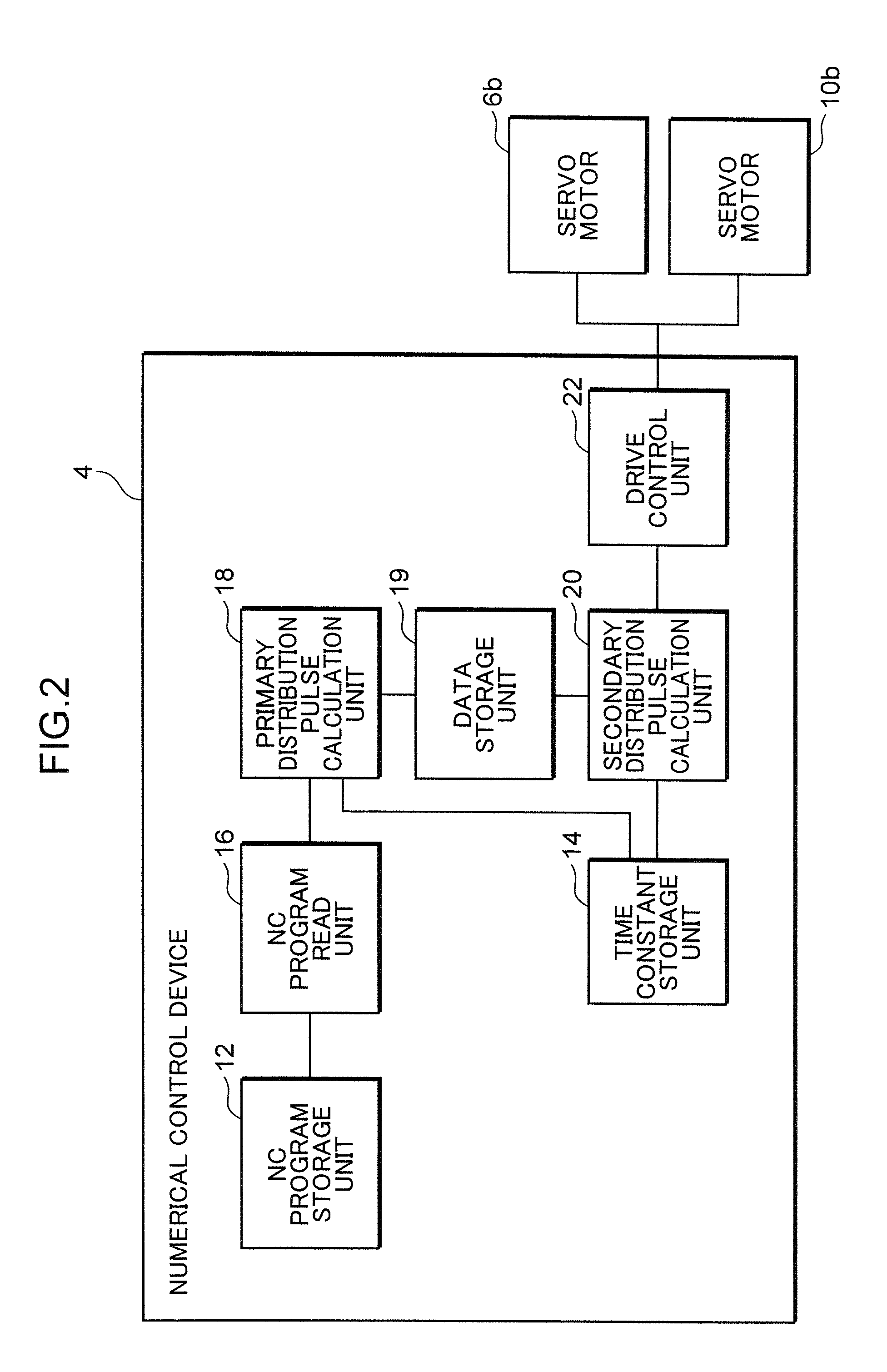
[0038]A configuration of a numerical control device 4 of a tool machine 2 according to the first embodiment of the present invention will be described below with reference to FIGS. 1 to 4.

[0039]The numerical control device 4 according to the first embodiment is provided at the tool machine 2 such as shown in FIG. 1. The tool machine 2 is a large turning machine capable of forming a spiral groove on an outer circumferential surface of a work W of a cylindrical shape. The tool machine 2 includes a work moving device 6 that rotates the work W about a C axis passing through an axial center thereof and a tool moving device 10 that moves a bit 8 serving as a tool for cutting the work W in the Z axis direction parallel to the axial center of the work W and in the X axis direction perpendicular to the Z axis direction. The direction about the C axis and the Z axis direction and X axis direction are included in the concept of movement direction in accordance with the ...

second embodiment

[0074](Second Embodiment)

[0075]A configuration of a numerical control device 34 for a tool machine 32 according to the second embodiment of the present embodiment will be described below with reference to FIG. 8 and FIG. 9.

[0076]The numerical control device 34 according to the second embodiment is provided, for example, at the tool machine 32 such as shown in FIG. 8. The tool machine 32 is provided with a work moving device 36 that moves the work W in the X axis direction on a horizontal plane and a tool moving device 40 that moves a tool 38 for cutting the work W in the Y axis direction perpendicular to the X axis direction on the plane. The X axis direction and the Y axis direction are included in the concept of the first movement direction and the second movement direction in accordance with the present invention.

[0077]The work moving device 36 is provided with a bed 36a fixed on an arrangement surface, a table 36b disposed on the bed 36a so that the table can move in the X axis ...


PUM


Abstract

A numerical control device includes a primary distribution pulse calculator that calculates primary distribution pulses obtained by distributing movement amounts in first and second directions included in a movement command of a work or a tool for each of predetermined calculation cycles. A secondary distribution pulse calculator calculates, for each movement direction, secondary distribution pulses obtained by distributing the primary distribution pulses of each calculation cycle calculated by the primary distribution pulse calculator, before and after corresponding calculation cycles within ranges of distribution sections across the corresponding calculation cycles and having an acceleration-deceleration time constant of the corresponding movement direction as a section width, and then accumulating the primary distribution pulses for each calculation cycle. A drive controller drives at least one of a tool moving device and a work moving device on the basis of the secondary distribution pulses calculated by the secondary distribution pulse calculator unit.

Description

BACKGROUND OF THE INVENTION[0001]1. Field of the Invention[0002]The present invention relates to a numerical control device for a tool machine.[0003]2. Description of the Related Art[0004]A turning device for turning a crankshaft is known as an example of a tool machine (see, for example, JP 2003-266202).[0005]The turning device disclosed in Patent Document 1 includes a work moving device that rotates a crankshaft serving as a work about a C axis, which is an axis of a main journal of the crankshaft, while supporting the crankshaft, and a tool moving device that moves a tool for machining linearly in the X axis direction perpendicular to the C axis and swings the tool about an α axis parallel to the C axis as a center. Further, in this turning device, as the crankshaft is rotated about the C axis by the work moving device, the linear movement of the tool in the X axis direction and the swinging thereof about the α axis performed by the tool moving device are NC controlled. As a resu...

Claims


Application Information

Patent Timeline
Patent Type & Authority Patents(United States)
IPC IPC(8): G05B19/18G05B19/29G06F19/00G05B13/02G05B11/28G05B11/01G05B11/32
CPCG05B19/4141G05B19/4103G05B2219/50013G05B2219/50052G05B2219/34167
Inventor NISHIBASHI, NOBUTAKA
Owner SHINNIPPON KOKI
Why Eureka
Try Eureka