
Surgical navigation enabled imaging table environment

a technology of imaging table environment and navigation system, applied in the field of surgical navigation system, can solve the problems of limiting the use of surgical navigation using these various technologies in some clinical applications, unwanted x-ray image artifacts, and limited acceptance of surgical navigation using these various technologies

Active Publication Date: 2013-07-09
STRYKER EURO OPERATIONS HLDG LLC
View PDF69 Cites 127 Cited by
  • Summary
  • Abstract
  • Description
  • Claims
  • Application Information

AI Technical Summary

Benefits of technology

The patent describes a surgical navigation system that uses magnetoresistance sensors to determine the position and orientation of a device. A navigation table can also be used with embedded tracking technology. The system can help improve the accuracy and precision of surgical procedures. In summary, the patent is about a technology that improves surgical precision through the use of magnetoresistance sensors.

Problems solved by technology

Surgical navigation using these various technologies are used today with limited acceptance in various clinical applications where an x-ray compatible medical table is used.
A major reason for the limited acceptance of surgical navigation during medical procedures is related to changes required in the normal surgical workflow that complicates the set-up, execution and turn-around time in the operating room.
Sensors of known navigation systems are not radiolucent, and if left in the imaging field of view will cause unwanted x-ray image artifacts.
EM and RF based navigation sensors have advantages over optical sensors in an intraoperative imaging environment (range, accuracy, non line-of-site), however, the composition of the medical table itself (carbon fiber) can introduce magnetic field distortions that can limit the use of these sensor technologies in some clinical applications.
Previous competitive surgical navigation system designs are stand alone systems that do not attempt to integrate non-radiolucent navigation sensors into the imaging environment.
If placed in the x-ray image field of view, the non-radiolucent sensors create distracting image artifacts.

Method used


Image

  • Surgical navigation enabled imaging table environment
  • Surgical navigation enabled imaging table environment
  • Surgical navigation enabled imaging table environment

Examples


Embodiment Construction

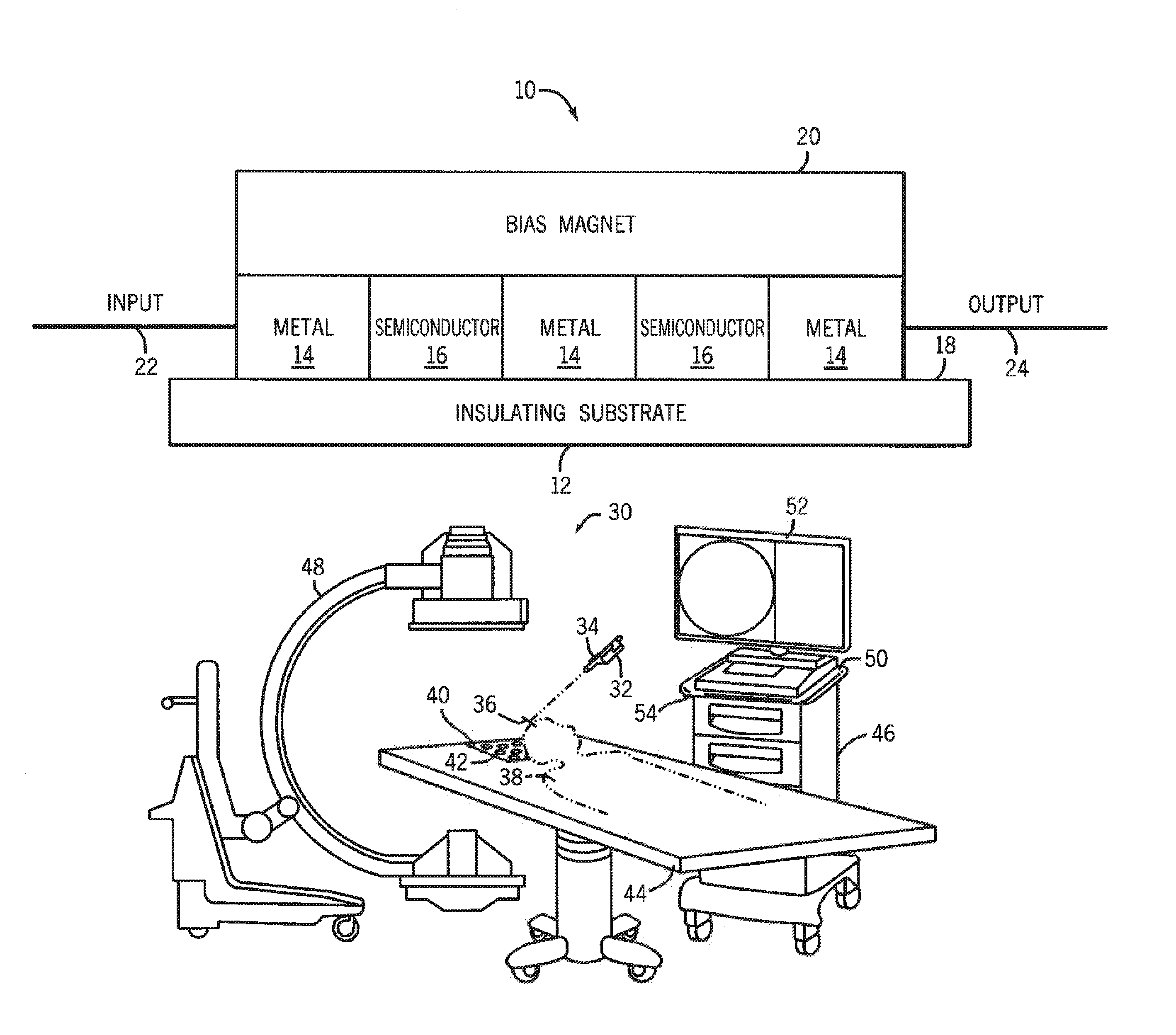
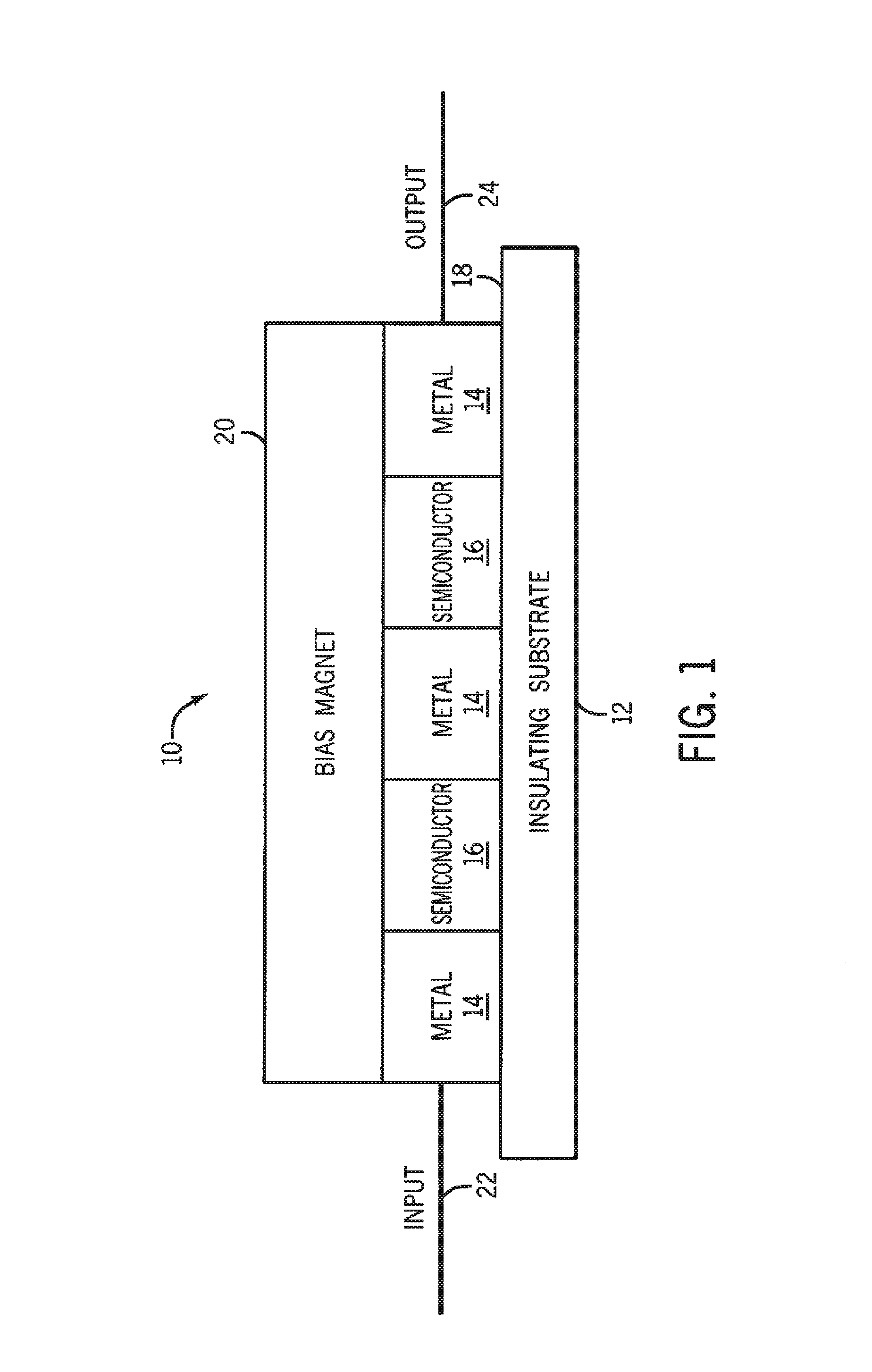
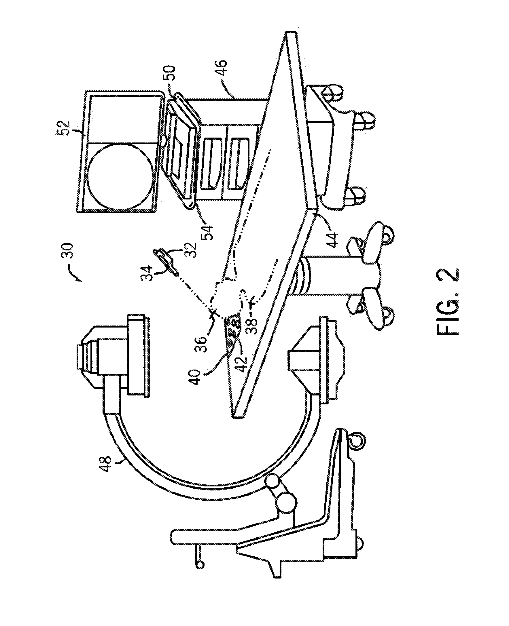
[0018]Referring now to the drawings, FIG. 1 illustrates an enlarged side view of an exemplary embodiment of a magnetoresistance sensor 10. A magnetoresistance device is a device that provides a change in electrical resistance of a conductor or semiconductor when a magnetic field is applied. The device's resistance depends upon the magnetic field applied. As shown in FIG. 1, the a magnetoresistance sensor 10 comprises an insulating substrate 12, an alternating pattern of a metal material 14 and a semiconductor material 16 deposited on a surface 18 of the insulating substrate, and a bias magnet material 20 deposited over the alternating pattern of metal material 14 and semiconductor material 16. The alternating pattern of metal material 14 and semiconductor material 16 creates a composite structure with alternating bands of metal material 14 and semiconductor material 16. At least one input connection contact 22 is coupled to the metal material 14 and at least one output connection co...


PUM


Abstract

A system for integrating radiolucent tracking sensors in a medical table, table mat, or surgical drape of a surgical navigation system, allowing the surgical navigation system to be less obtrusive in a surgery environment. A plurality of radiolucent magnetoresistance sensors are integrated into a table, table mat, or surgical draping of a surgical navigation system for improving surgical navigation workflow and eliminating image artifacts from intraoperative images. The plurality of radiolucent magnetoresistance sensors may be located within a table or adjacent to a table surface.

Description

BACKGROUND OF THE INVENTION[0001]This disclosure relates generally to surgical navigation systems, and more particularly to a system for integrating radiolucent tracking sensors in a medical table.[0002]Surgical navigation systems track the precise position and orientation of surgical instruments, implants or other medical devices in relation to multidimensional images of a patient's anatomy. Additionally, surgical navigation systems use visualization tools to provide the surgeon with co-registered views of these surgical instruments, implants or other medical devices with the patient's anatomy.[0003]The multidimensional images may be generated either prior to (pre-operative) or during (intraoperative) the surgical procedure. For example, any suitable medical imaging technique, such as X-ray, computed tomography (CT), magnetic resonance (MR), positron emission tomography (PET), ultrasound, or any other suitable imaging technique, as well as any combinations thereof may be utilized. ...

Claims


Application Information

Patent Timeline
Patent Type & Authority Patents(United States)
IPC IPC(8): A61B5/05G01R33/00G01R33/02
CPCA61B19/5244A61G13/10G01B7/003G01B7/30G01R33/091G01R33/095A61B2017/00915A61B2017/0092A61B2019/5251A61G2210/50A61B34/20A61B2034/2051
Inventor JENSEN, VERNON THOMASHUBER, WILLIAM H.
Owner STRYKER EURO OPERATIONS HLDG LLC
Learn More