Unlock instant, AI-driven research and patent intelligence for your innovation.

Induction motor parameter identification

a technology of induction motor and parameter identification, which is applied in the direction of digital computer details, testing circuits, instruments, etc., can solve the problems of inability to carry out identification procedures, inability to perform identification runs with load, and cumbersome and sometimes even impossibl

Active Publication Date: 2013-07-09
ABB (SCHWEIZ) AG
View PDF11 Cites 4 Cited by
  • Summary
  • Abstract
  • Description
  • Claims
  • Application Information

AI Technical Summary

Benefits of technology

The present disclosure provides a method and apparatus for accurately estimating the main inductance and rotor time constant without needing to increase the accuracy of voltage measurement. This allows for better control and performance of the motor. Additionally, the method can also determine the rotor resistance and calculate threshold voltages more accurately than before.

Problems solved by technology

In some situations, the load connected to the machine causes some restrictions to the drive so that the identification procedure cannot be carried out.
The load connected to the controlled motor produces counter torque, which disturbs the identification run to the extent that the identification procedure does not provide accurate results that would enable precise control of the motor.
It might also be possible that the identification run cannot be performed with the load at all due to maximum speed and / or maximum torque limits set for the load.
This is often cumbersome and sometimes even impossible if the machine to be controlled is an integral part of the mechanics of the load.
A disadvantage of the known stand-still identification methods is that the measurement of main inductance LM and the rotor time constant τr (=LM / RR) depending thereon is very tricky because the machine cannot be rotated.
This means that the corresponding changes in the magnetizing current im are relatively small, and thus the response from the main inductance to the test pulses is poor.
On the other hand, the rated values are not necessarily exact so that the values obtained for the main inductance and rotor time constant with the known stand-still identification methods are inaccurate, which is reflected as a poorer performance of the control when compared to the performance achieved with parameters obtained in identification runs performed with rotating machines.
The increase in voltage accuracy is hard to achieve since, due to reduced costs, the output voltage in frequency converters is typically calculated using a measured DC bus voltage and output switch combination.
In this kind of measurement, commutation delays and threshold voltages cause inaccuracies to the voltage measurement.

Method used


Image

  • Induction motor parameter identification
  • Induction motor parameter identification
  • Induction motor parameter identification

Examples


Embodiment Construction

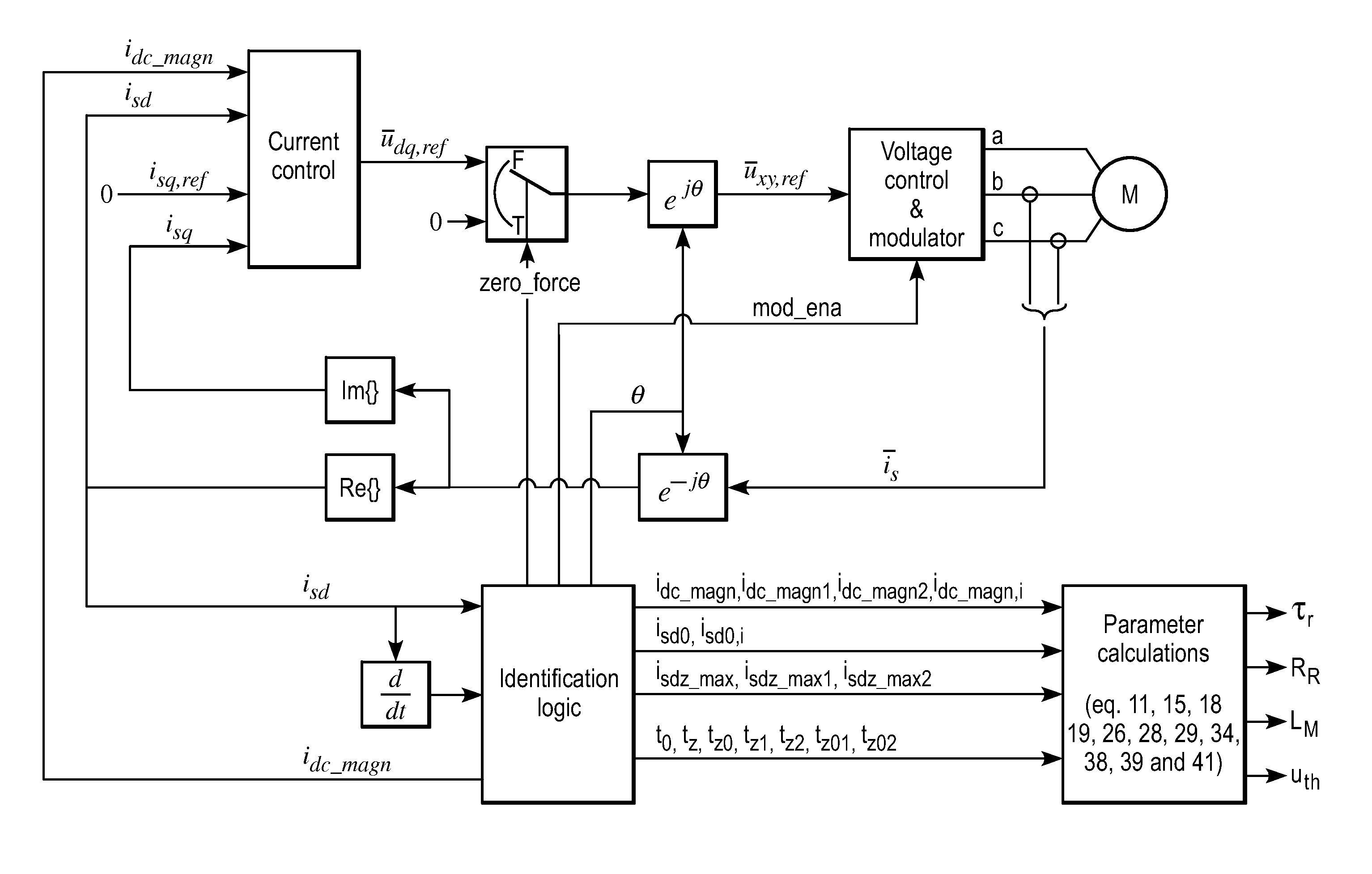
[0020]Exemplary embodiments of the present disclosure provide a method and an arrangement for implementing the method of identifying motor parameters.

[0021]Exemplary embodiments of the present disclosure are based on the idea of indirect measurement of decaying counter voltage of an induction machine. With the method and apparatus of the disclosure, the parameters required for control of an induction machine can be identified without rotating the machine.

[0022]The method and apparatus of the present disclosure can eliminate the above disadvantages relating to inaccuracies of estimated main inductance and rotor time constant without needing to increase the accuracy of voltage measurement. The present disclosure provides a way to determine directly the rotor time constant, after which the main inductance can also be estimated if the rotor resistance is known. An exemplary embodiment of the present disclosure also provides a method for determining the rotor resistance. Further, an exem...


PUM


Abstract

A method and an arrangement are provided for identifying parameters of an induction machine when the induction machine is connected to the output phases of a voltage source inverter and the induction machine is in standstill state. The method includes providing a DC magnetization current (idc<sub2>—< / sub2>magn) to the induction machine with the inverter, controlling the power semiconductors of the inverter to an off-state, controlling all the output phases of the inverter to the same potential to provide a zero voltage vector, measuring the stator current (isd) during the zero voltage vector, and determining parameters of the induction machine from the stator current (isd) measured during the zero voltage vector.

Description

RELATED APPLICATIONS[0001]This application claims priority under 35 U.S.C. §119 to European Patent Application No. 09164537.4 filed in Europe on Jul. 3, 2009, the entire content of which is hereby incorporated by reference in its entirety.FIELD[0002]The present disclosure relates to a method of identifying motor parameters, and more particularly to a method with which parameters of an induction motor can be identified without rotating the motor. The present disclosure also relates to an arrangement for identifying parameters of an induction motor, and more particularly to an arrangement for identifying parameters of an induction motor when the induction motor is in a standstill state.BACKGROUND INFORMATION[0003]When a frequency converter or a similar device is used for controlling the motion of a motor, it is desirable for the motor parameters be known. The machine parameters are used in control algorithms of the converter for accurate control of the load. The parameters of the mach...

Claims


Application Information

Patent Timeline
Patent Type & Authority Patents(United States)
IPC IPC(8): G01R15/00
CPCH02P21/14H02P21/145H02P23/14G01R31/343H02P21/16
Inventor HEIKKILA, SAMULI
Owner ABB (SCHWEIZ) AG