
System and method for augmented reality inspection and data visualization

a technology of augmented reality and data visualization, applied in the direction of instruments, specific gravity measurement, machines/engines, etc., can solve the problems of inability to bring the tip to the same location, minimal information about the location and pose of the borescope is available to the operator, and the difficulty of inspection of complex parts and structures

Active Publication Date: 2013-07-16
GE INFRASTRUCTURE TECH INT LLC
View PDF38 Cites 29 Cited by
  • Summary
  • Abstract
  • Description
  • Claims
  • Application Information

AI Technical Summary

Benefits of technology

Enhances inspection accuracy, reduces operator dependency, enables automation, and improves damage reporting by providing precise location and pose information of the probe, facilitating efficient and guided inspection and repair processes.

Problems solved by technology

Inspection of complex parts and structures generally require immense inspector skill and experience.
However, once the probe is inserted into a borescope inspection hole, minimal information about a location and pose of a tip of the borescope is available to an operator.
Moreover, during tip change scenarios, it is almost impossible to bring the tip to the same location.

Method used


Image

  • System and method for augmented reality inspection and data visualization
  • System and method for augmented reality inspection and data visualization
  • System and method for augmented reality inspection and data visualization

Examples


Embodiment Construction

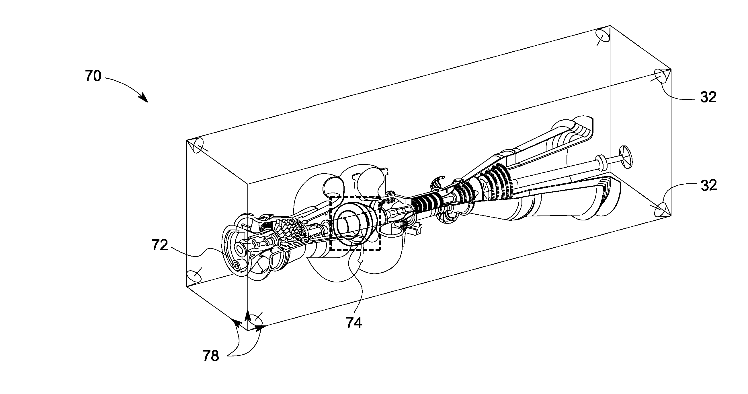
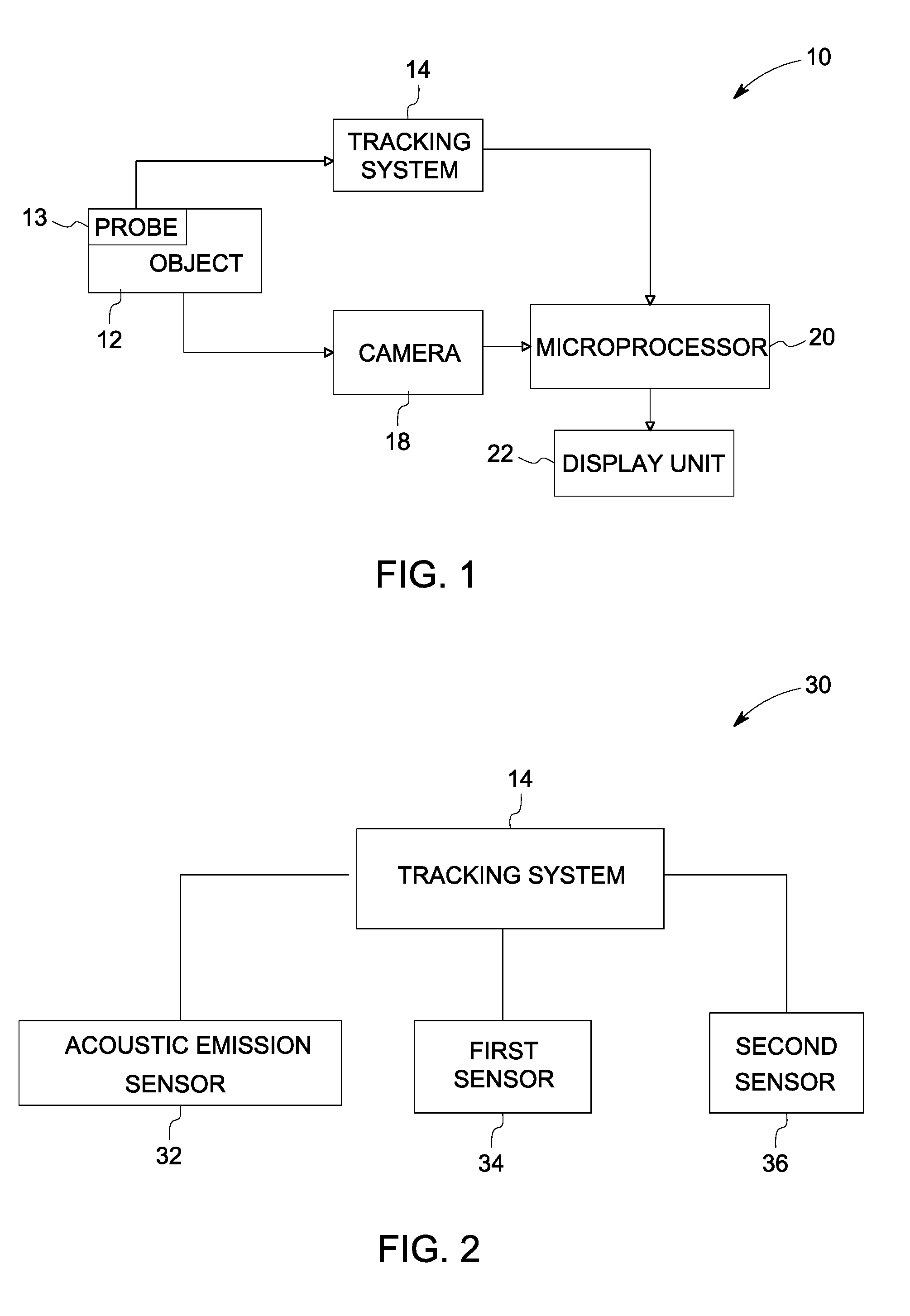
[0018]As discussed in detail below, embodiments of the invention include a system and method for non-destructive inspection of an object. The system and method disclosed herein generate an augmented reality image using an improved tracking system for inspection. As used herein, ‘augmented reality image’ refers to an image that includes real world data superimposed with computer generated data. Non-limiting examples of the object include aircraft engines, gas turbines, steam turbines, diesel engines and a living organism.

[0019]Turning to the drawings, FIG. 1 is a high-level block diagram representation of an augmented reality system 10 to inspect an object 12. A tracking system 14 is employed to identify a 3D location and position of a probe 13 inserted into the object 12. In a particular embodiment, the probe 13 includes a borescope or an endoscope. The camera 18 captures a view of the object 12 as a real image. In a particular embodiment, the camera 18 captures a monocular view. In...


PUM

PropertyMeasurementUnit
diameteraaaaaaaaaa
diameteraaaaaaaaaa
diameteraaaaaaaaaa

Abstract

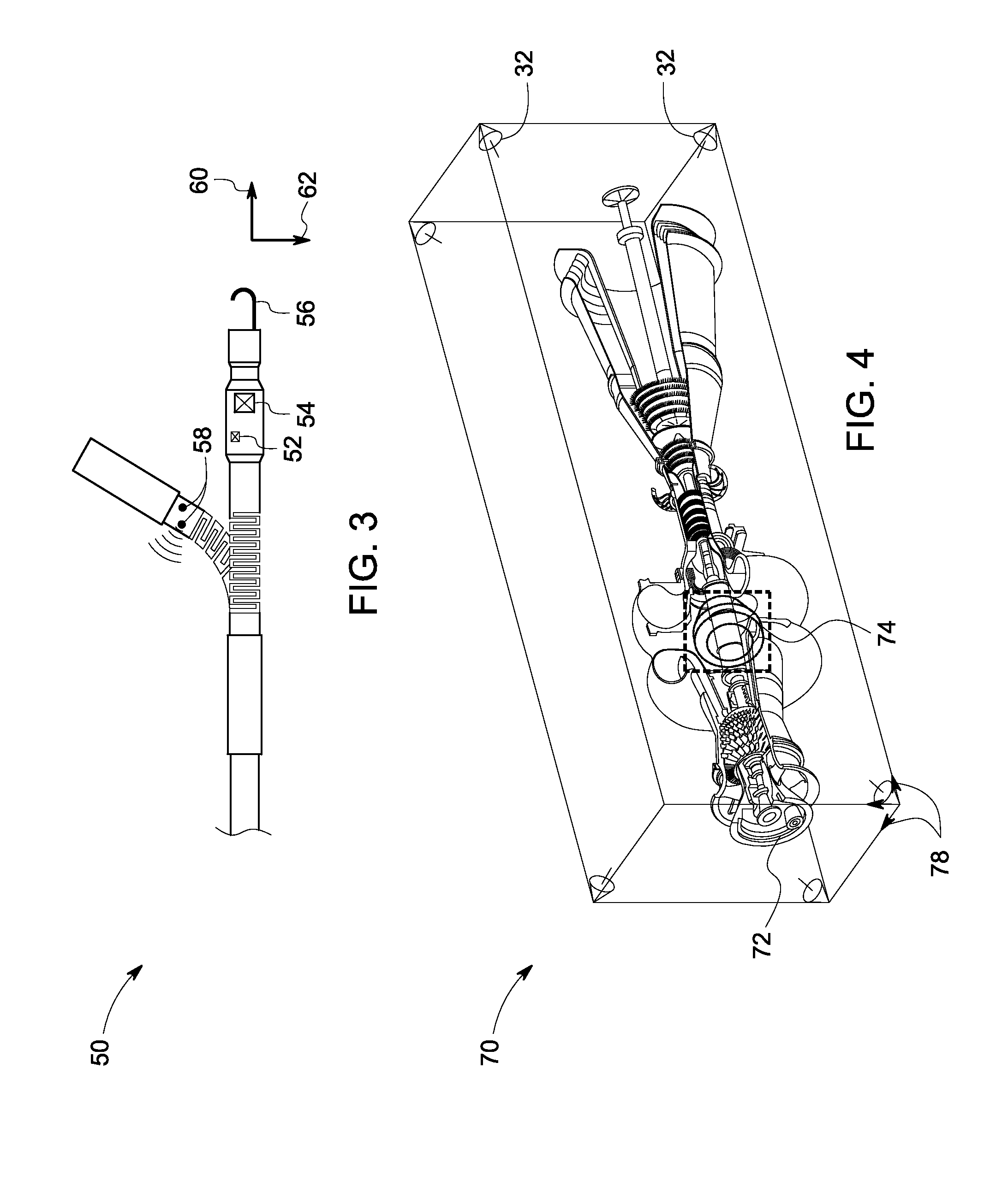
A 3D tracking system is provided. The 3D tracking system includes at least one acoustic emission sensor disposed around an object. The acoustic emission sensor is configured to identify location of a probe inserted into the object based upon time of arrival of an acoustic signature emitted from a location on or near the probe. The 3D tracking system also includes a first sensor configured to detect an elevation of the probe. The 3D tracking system further includes a second sensor configured to detect an azimuth of the probe.

Description

CROSS REFERENCE TO RELATED APPLICATIONS[0001]This application claims the benefit of a priority under 35 USC 119 to Indian Patent Application No. 3014 / CHE / 2007, filed Dec. 18, 2007, entitled “SYSTEM AND METHOD FOR AUGMENTED REALITY INSPECTION AND DATA VISUALIZATION”, the entire contents of which is hereby incorporated by reference.BACKGROUND[0002]The invention relates generally to non-destructive inspection techniques and, more particularly, to inspection techniques employing augmented reality.[0003]Inspection techniques are commonly used in a variety of applications ranging from aircraft industry, health industry to security applications. Inspection of complex parts and structures generally require immense inspector skill and experience. Borescope inspection is one of the commonly used sources of information for monitoring of industrial infrastructure due to easy access to in-service parts and reduced downtime. Condition based maintenance strategies on gas turbine and related system...

Claims


Application Information

Patent Timeline
Patent Type & Authority Patents(United States)
IPC IPC(8): G01N29/06G06K9/22G06K9/20
CPCF01D21/003G01S5/30H04N13/183
Inventor SENGUPTA, ANANDRAJKUMAR, VINOD PADMANABHANGORAVAR, SHIVAPPA NINGAPPA
Owner GE INFRASTRUCTURE TECH INT LLC
Learn More