Ultrasound diagnosis apparatus

a technology of ultrasound and diagnostic equipment, applied in the field of ultrasound diagnostic equipment, can solve the problems of deterioration of image data quality at the areas apart from the transmission focusing point, inability to narrow the beam width of the transmission focusing area, and remarkably deterioration of time resolution (frame rate) for acquiring image data, etc., to achieve uniform thin width, high sensitivity, and high accuracy

Active Publication Date: 2013-07-16
TOSHIBA MEDICAL SYST CORP
View PDF18 Cites 12 Cited by
  • Summary
  • Abstract
  • Description
  • Claims
  • Application Information

AI Technical Summary

Benefits of technology

[0013]To solve the above-mentioned conventional problems and defects, the present invention provides a new ultrasound diagnosis apparatus that can acquire ultrasound image data having excellent spatial resolution and contrast resolution by electrically controlling focusing points of transmission / reception waves so as to form transmitting beams and receiving beams having a substantially uniform thin beam width along an elevation direction in an object.
[0028]In the ultrasound diagnosis apparatus consistent with the present invention, transmission ultrasounds emitted from a plurality of transmitting transducers are focused at a hypothetical point sound source, and reflect at the observing point positioned in transmission wave-fronts propagated from the hypothetical point sound source. The reflected ultrasounds are received through a plurality of receiving transducers. The acquired receiving signals through the plurality of receiving transducers have performed receiving phase compensation for focusing and summation and have further performed transmitting wave-front compensation and summation. By doing so, it becomes possible to generate transmission beams and reception beams that have substantially uniform thin width along an elevation direction to an object with high accuracy and high sensitivity. By successively renewing the hypothetical point sound source, it becomes possible to utilize echo signals reflected from the observing points in the transmitting wave-front area to the maximum extent possible. Further, it becomes possible to generate and display excellent image data of high spatial resolution and high contrast resolution in a high signal to noise (S / N) ratio without reducing time resolution (frame rate) of the image data.

Problems solved by technology

Typically, when a strong beam focusing is executed by using a transducers group having a large width used for a transmission (i.e. a large transmission aperture), a conspicuous deterioration of image data quality occurs at the areas apart from the transmission focusing point.
On the contrary, when a weak beam focusing is executed by using a small transmission aperture, it becomes impossible to narrow a beam width for a transmission focusing area.
Accordingly, the proposed multi-stages focusing method has a problem in that a time resolution (frame rate) for acquiring the image data is remarkably deteriorated.
Further, the proposed multi-stages focusing method has another problem in that the transmission energy emitted into the object can not be effectively used since the receiving signals are acquired at areas other than the transmission focusing area.

Method used


Image

  • Ultrasound diagnosis apparatus
  • Ultrasound diagnosis apparatus
  • Ultrasound diagnosis apparatus

Examples


Embodiment Construction

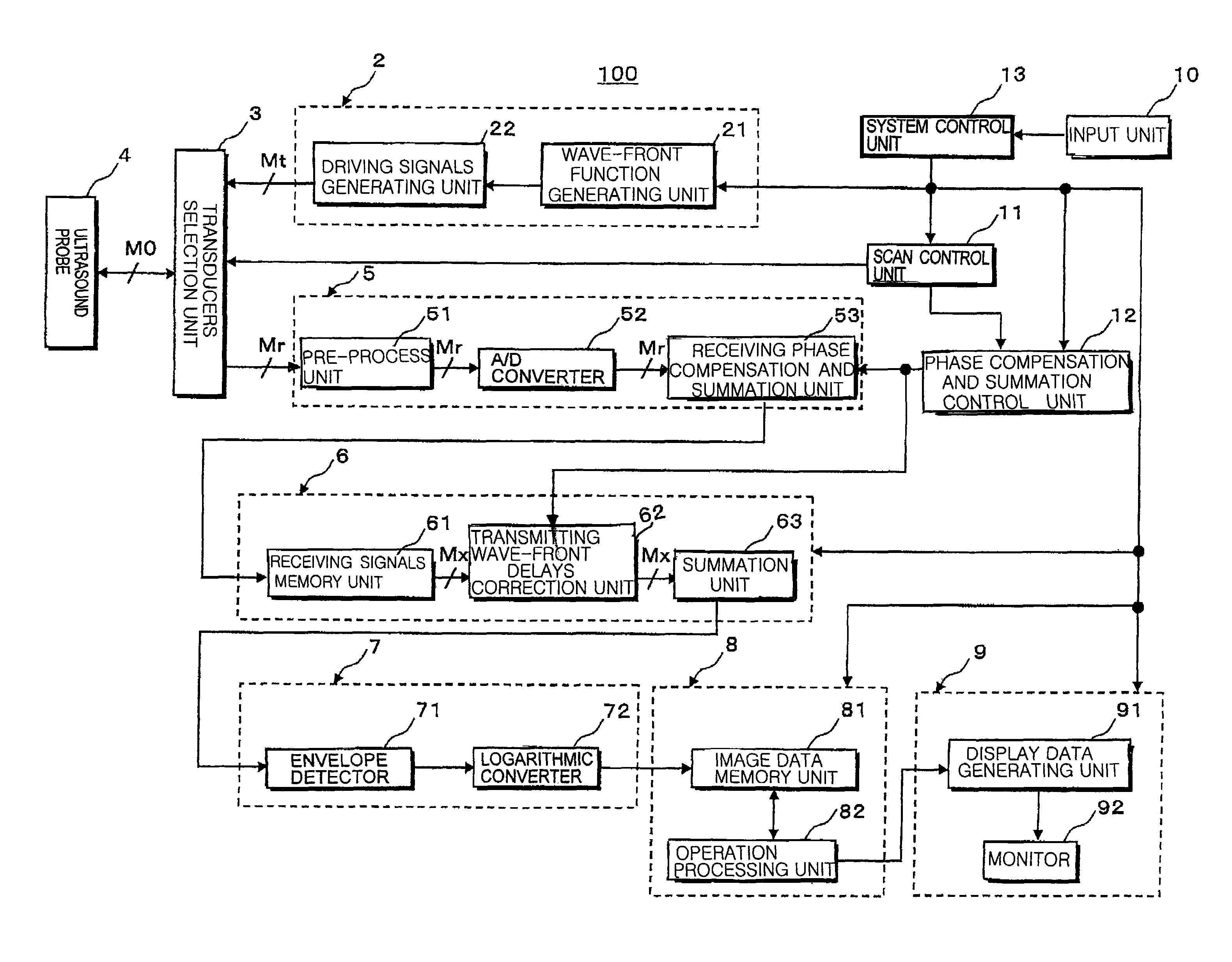
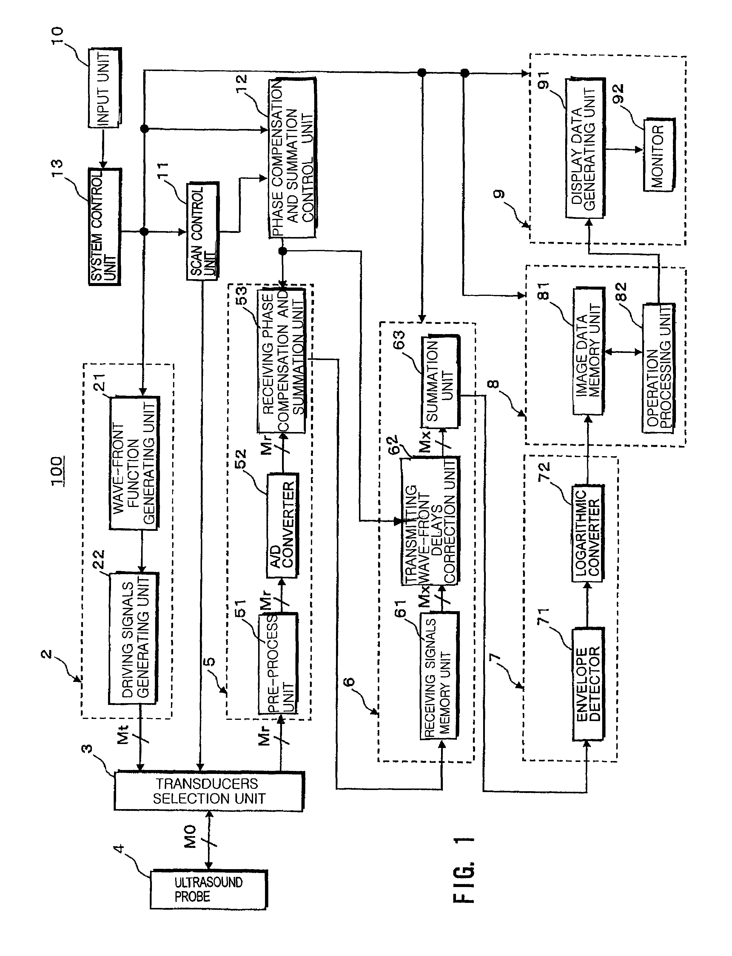
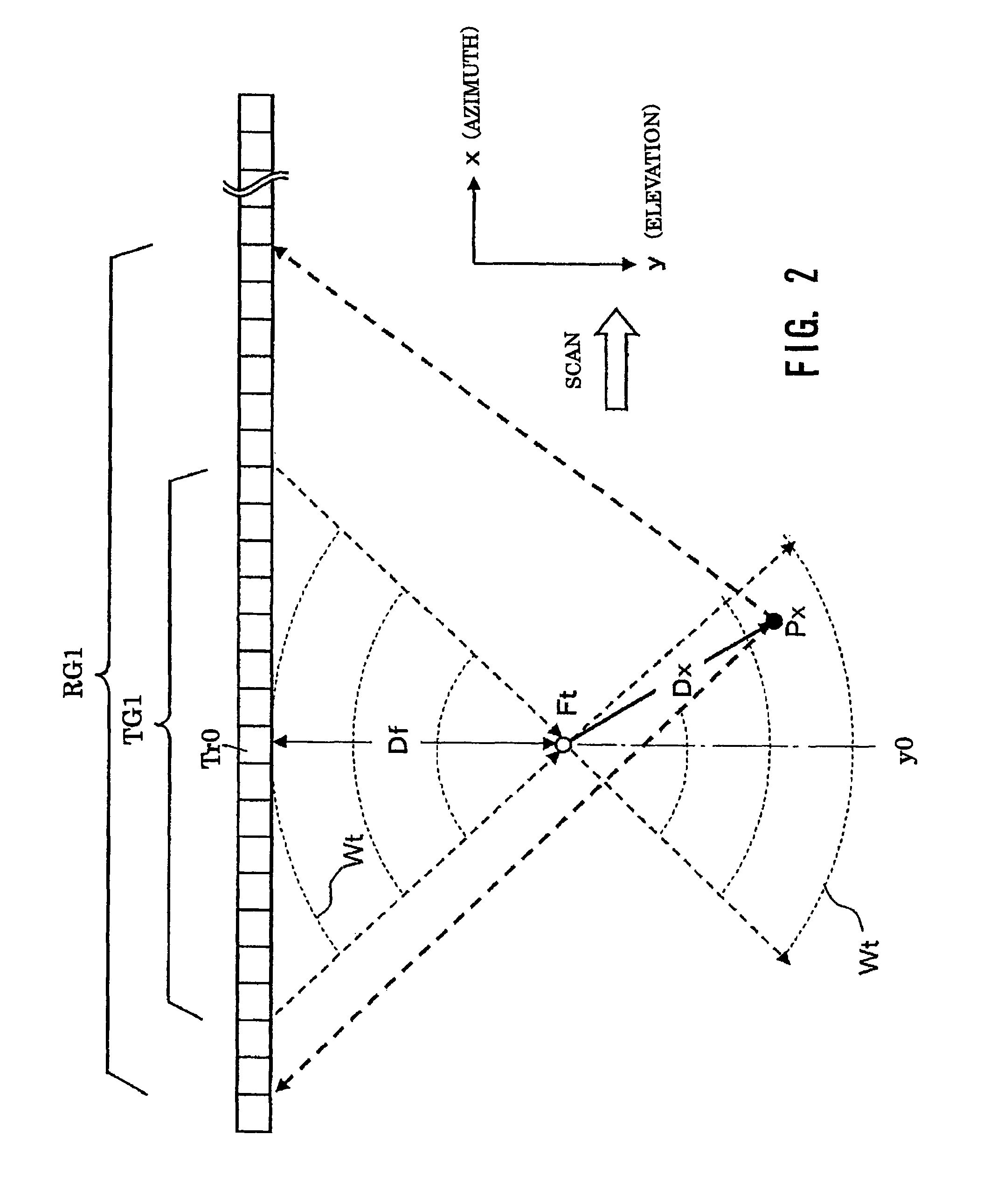
[0044]The preferred embodiments of an ultrasound diagnosis apparatus consistent with the present invention, a plurality of hypothetical point sound sources is formed at optional position by focusing transmission ultrasounds emitted from a plurality of transducers at a prescribed transmission converging point. Based on the transmitting ultrasound wave-fronts emitted from the hypothetical point sound source, echo ultrasounds reflected at an optionally designated observing point are received through a plurality of transducers constructing a receiving transducer group. The acquired receiving signals of a plurality of channels have performed receiving phase compensation for focusing and summation so as that each of the observing points becomes a receiving focusing point. Further, a plurality of receiving signals acquired by successively shifting a pair of the plurality of the receiving transducer groups and the transmitting transducer group along an arrangement direction of the plurality...


PUM


Abstract

An ultrasound diagnosis apparatus that can acquire ultrasound image data having excellent spatial resolution and contrast resolution by electrically controlling focusing points of transmission / reception waves so as to form transmitting beams and receiving beams having substantially uniform thin beam width along an elevation direction. Ultrasounds emitted from a prescribed number of transducers are focused at a hypothetical point sound source. Wave-fronts reflect at a plurality of observing points. Ultrasounds reflected at the observing points are received through a prescribed number of transducers generating a plurality of channels of receiving signals, which are focused by performing phase compensation and summation so that the observing point becomes a reception focusing point. The receiving signals are focused to correct transmitting delays due to propagation distances between the transmitting focusing point and the observing points.

Description

CROSS-REFERENCE TO RELATED APPLICATIONS[0001]This application claims priority from, and the benefit of, Japanese Patent Application No. 2008-93812, filed on Mar. 30, 2008, the contents of which are expressly incorporated herein by reference in their entirety.BACKGROUND OF THE INVENTION[0002]1. Field of the Invention[0003]The present invention relates to an ultrasound diagnosis apparatus capable of generating ultrasound images of a high spatial resolution and a high contrast resolution, and more particularly, to an ultrasound diagnosis apparatus capable of transmitting and receiving transmission beams and reception beams, each having substantially uniform thin beam width along an elevation direction, from and to ultrasound transducers.[0004]2. Description of the Related Art[0005]An ultrasound diagnosis system transmits ultrasound pulses from ultrasound transducers (hereinafter “transducers”) installed in a head portion of the ultrasound probe to an object, such as a patient. The tran...

Claims


Application Information

Patent Timeline
Patent Type & Authority Patents(United States)
IPC IPC(8): A61B8/00
CPCG01S7/52046G01S15/8927G01S7/52095G01S7/52047G01S15/8997
Inventor HIRAMA, MAKOTO
Owner TOSHIBA MEDICAL SYST CORP
Why Eureka
Try Eureka