Audio-peak limiting in slow and fast stages

a technology of audio peak limiting and slow and fast stages, applied in the field of audio digital signal processing and audio peak limiting, can solve the problems of significant alteration of spectral characteristics and perceived timbre of audio, and achieve the effect of reducing gain

Active Publication Date: 2013-07-16
DOLBY LAB LICENSING CORP
View PDF12 Cites 8 Cited by
  • Summary
  • Abstract
  • Description
  • Claims
  • Application Information

AI Technical Summary

Benefits of technology

[0014]The second variable-gain reduction may include delaying the audio signal, finding a peak among the delayed audio signal, calculating a fast gain from a found peak, and modifying the delayed audio signal with the calculated fast gain. The delaying may include buffering the audio signal, and the finding may include examining the buffered audio signal. Apparent directions of respective virtual images and directions of respective matrix-encoded audio signals may be maintained. The second variable-gain reduction may produce less audible spectral splatter than a method as constituted above except lacking the delaying. The buffering may include providing a finite amount of time for the second variable-gain reduction to slew to meet a peak beyond the threshold. The delaying may include delaying for at least 1 ms and may include delaying for about 1.5 ms. Finding the peak may include determining maximums in respective temporal segments of the delayed audio signal, delaying the audio-signal maximums, and computing a control signal for reducing the gain of the audio signal, based on the delayed maximums.

Problems solved by technology

Multi-band limiting is often used to achieve significant amounts of peak limiting, but with the potential of significantly altering the spectral characteristics and perceived timbre of the audio.

Method used


Image

  • Audio-peak limiting in slow and fast stages
  • Audio-peak limiting in slow and fast stages
  • Audio-peak limiting in slow and fast stages

Examples


Embodiment Construction

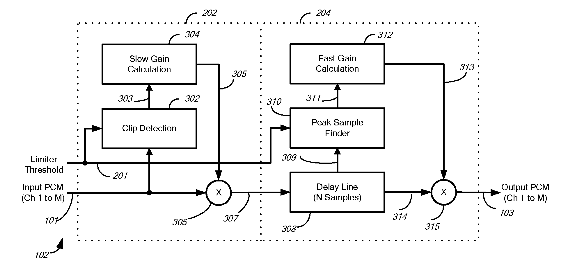
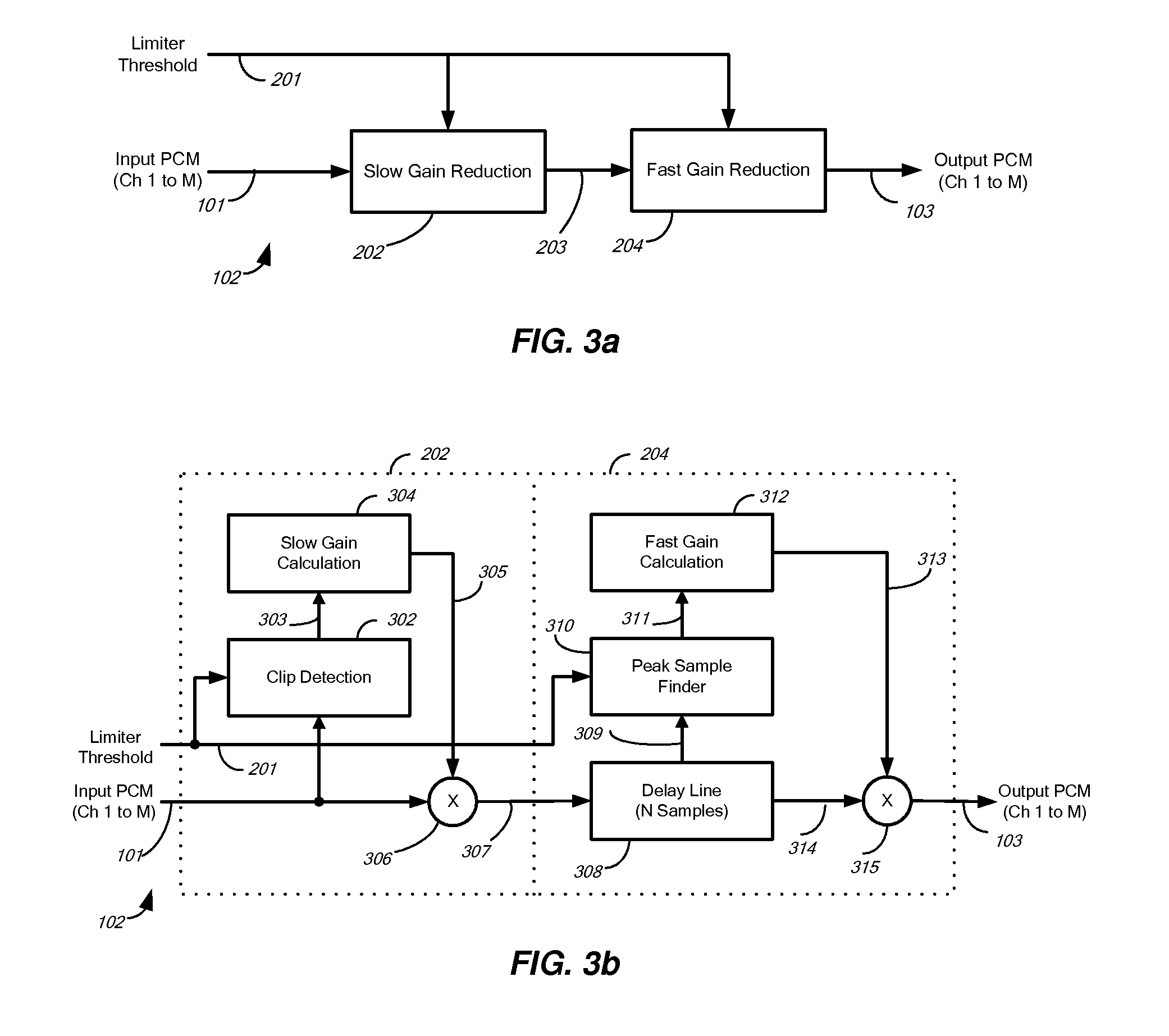
[0052]FIG. 3a illustrates a two-stage audio peak limiter 102 according to one embodiment of the invention. The peak limiter 102 includes a slow gain reducer 202 and a fast gain reducer 204. The slow gain reducer 202 receives as input a threshold signal 201 and an audio signal 101 and produces as intermediate audio signal 203. The fast gain reducer 204 receives as input the intermediate audio signal 203 as well as the threshold signal 201 and produces as output the audio signal 103.

[0053]The peak limiter 102 operates as follows: The slow gain reducer 202 receives one or more audio channels by means of the input signal 101 and a signal representing the limiter threshold by means of the threshold signal 201. The absolute peak(s) of the audio channel(s) may exceed the limiter threshold.

[0054]The fast gain reducer 204 outputs signal 103, the possibly limited audio channel(s) of the input audio signal 101. The limiter 102 limits (gain reduces) any absolute peaks in the input audio signal ...


PUM


Abstract

A method and apparatus for limiting the absolute magnitude of an audio signal. The method may include firstly variable-gain reducing the gain of an audio signal, and then secondly variable-gain reducing the gain of the audio signal faster than the first variable-gain reduction, thereby limiting the absolute magnitude of the audio signal to a threshold. The first variable-gain reduction may include variable-gain reducing the gain of the audio signal in a first stage, and the second variable-gain reduction may include variable-gain reducing the gain of the audio signal in a second stage that reduces the gain faster than the first stage. The second variable-gain reduction may include delaying the audio signal, finding a peak among the delayed audio signal, calculating a fast gain from a found peak, and modifying the delayed audio signal with the calculated fast gain.

Description

TECHNICAL FIELD[0001]This invention generally relates to audio digital signal processing and audio peak limiting. More particularly, the invention relates to variable-gain reduction of an audio signal to limit the audio signal to a threshold.BACKGROUND ART[0002]Audio peak limiting has been a fundamental part of the production, transmission and reproduction of audio for over 50 years. As FIG. 1 shows, in its most basic form an audio peak limiter provides an input to output signal level characteristic such that the output voltage is equal to the input voltage up to the peak-limiting threshold. For input audio signals with amplitude above the threshold, the output audio-signal level is constrained (limited) so as not to exceed the threshold. As with other dynamic gain control systems for audio, the method of modifying the gain has a significant impact on the nature and audibility of artifacts introduced into the output audio signal.[0003]In one of its earliest uses, audio peak limiting...

Claims


Application Information

Patent Timeline
Patent Type & Authority Patents(United States)
IPC IPC(8): H03G3/00H03G3/20
CPCH03G7/007H03G11/008
Inventor SMITHERS, MICHAEL JOHNCROCKETT, BRETT GRAHAMMCGRATH, DAVID STANLEY
Owner DOLBY LAB LICENSING CORP
Why Eureka
Try Eureka