Biostable neuroelectrode

a neuroelectrode and biostable technology, applied in the field of multi-channel neuroelectrodes, can solve the problems of increased electrical losses in each electrode, difficulty in access, and high current required for the stimulation of neurons, and achieve the effect of ensuring the stability of neuroelectrodes

Active Publication Date: 2013-07-16
ORTMANN VALERIJ
View PDF10 Cites 33 Cited by
  • Summary
  • Abstract
  • Description
  • Claims
  • Application Information

AI Technical Summary

Benefits of technology

[0009]It is one the object of this invention to provide a penetrating neuro-electrode for the stimulation and signal derivation from the neuronic tissues, which assures the dependable and stable functioning of the neuro-implant over extended periods of time.
[0010]So that the electrical power loss in the electrodes can be kept as low as possible, metal conductors are used for connecting electrodes to the associated electronic components. The technical challenge with this is to connect the large number (100 to 1000) of required conductors with the electronic components, and is solved by a special method.
[0011]The connections are realized because the conductors become the basic element of neuro-electrodes, because of which the total volume of connecting points is minimized. This makes possible a space-saving construction of large electrode arrays with hundreds, or even thousands of electrodes.
[0013]So that the stability of neuro-electrodes is assured over extended periods, the interior of the micro-capillaries is filled with a bioactive substance, which prevents growth on electrodes. Filling also takes place by a special vacuum process.

Problems solved by technology

In most cases, these are located relatively deeply underneath the cortical surface and are difficult to access.
The main disadvantage of this solution is that very high currents are required for the stimulation of neurons in order to address the deeply located neurons.
The employment of these arrays as neuro-stimulators discloses some disadvantages of this solution: electrical losses in each electrode increase because of the use of doped silicon as the electrode material, because impedance can lie within the range of 300 to 800 KOhm.
Therefore, energy consumption of the neuro-implant increases on the one hand and, on the other hand, the thermal stress on the nervous tissue in the vicinity of the electrodes increases.
A further problem is posed by the manufacture of electrode profiles, such as shown in FIG. 1.
Although this embodiment has excellent electrical properties, it is only suitable for acute employment, because it is not possible to construct the electrodes in a fully implementable manner because of the enormous size of the connecting elements.
At the same time, the stiffness of the described electrodes is not sufficient for penetrating the nerves.
The stability over extended time causes another common problem of neuro-electrodes.
Because of an interaction with biological tissue, a sort of a protective layer of neuroglial cells grows on the electrodes, which leads to a clear increase in stimulation thresholds and to the worsening of the signal quality.
Because the desired service life of neuro-implants is more than 10 years, this can result in the complete failure of the neuro-stimulator.

Method used


Image

  • Biostable neuroelectrode
  • Biostable neuroelectrode
  • Biostable neuroelectrode

Examples


Embodiment Construction

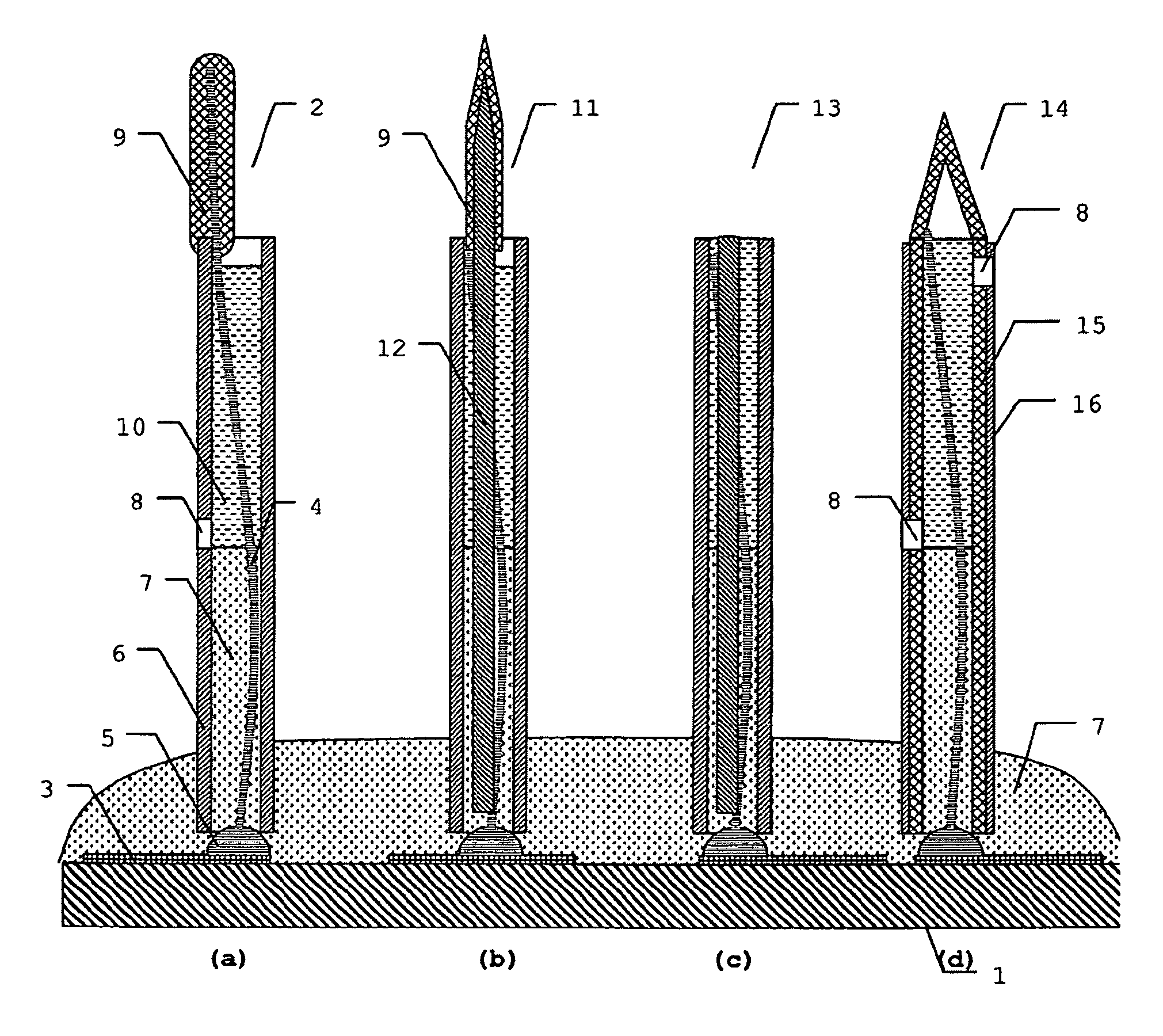
[0023]FIG. 1 represents a possible use of neuro-electrodes for the stimulation and derivation of signals in cortical layers of the brain. The structure of the visual cortex is schematically represented in several layers, with FIG. 1 showing the transition between the primary cortex V1 and the secondary cortex V2, and sublayers 4A, 4B, and 4C. It is known from neuro-physiological investigations that different layers of the cortex are responsible for different forms of representation of the information. For example, in the case of the visual cortex the information is conducted from so-called P and M receptor fields, which are responsible for contrast and movement, of the retina into the layer IV. But information regarding absolute brightness goes into the layer I. Since the layer I lies on the surface of the brain, and the layer IV at a depth of approximately 1 to 2 mm, it is required to have electrodes of different length in an electrode array. However, since the depth of the layer I...


PUM


Abstract

A device for deriving electrical signals or for electrically simulating neuronal tissue. Neuroelectrodes form an interface between the biological tissue and technical systems. Existing neuroelectrodes for contacting low-lying neuronal layers diminish their properties by the interaction with biological tissue. In order to improve the long-time behavior, neuroelectrodes filled with bioactive substances are used. The neuroelectrode is formed on a flexible or rigid substrate with the aid of a line and of a microcapillary. The inside of the microcapillary serves as a container for the bioactive substance. The biostable neuroelectrode is used for deriving electrical signals or for electrically stimulating neuronal tissue in the fields of neurology and neurophysiology.

Description

BACKGROUND OF THE INVENTION[0001]1. Field of the Invention[0002]This invention relates to a device for electrical stimulation and signal derivation from neuronic tissue. More accurately stated, this invention relates to a multi-channel neuro-electrode for stimulating neurons in interior neuronic layers, or interior fibers of a nerve, which is suitable for extended time applications because of a particular stability.[0003]2. Discussion of Related Art[0004]During development of neuro-implants for correcting handicaps such as loss of hearing or blindness, a practical possibility for correcting further neurological handicaps, such as paraplegic handicaps, was recorded. While the first cochlear and retinal implants use sensory neurons in the sensory organs, such as the cochlea or retina, for transmitting information, in other applications the requirement exists for making a direct connection with neurons of different cortical regions. In most cases, these are located relatively deeply un...

Claims


Application Information

Patent Timeline
Patent Type & Authority Patents(United States)
IPC IPC(8): A61N1/00A61B5/04
CPCA61B5/04001A61N1/0541A61B5/24
Inventor ORTMANN, VALERIJ
Owner ORTMANN VALERIJ
Why Eureka
Try Eureka