

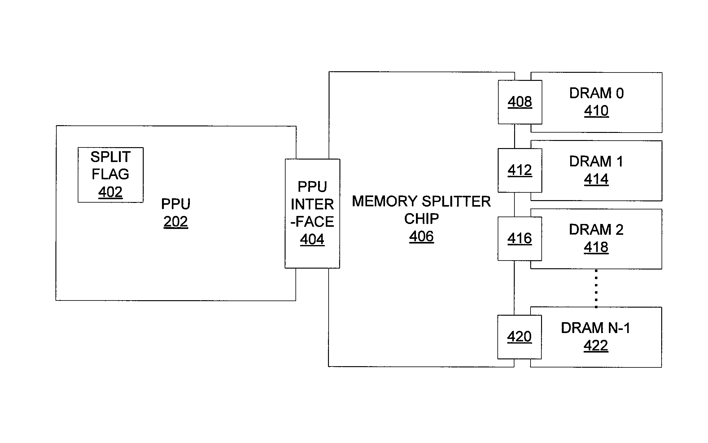
Increasing memory capacity of a frame buffer via a memory splitter chip
a memory splitter and frame buffer technology, applied in the field of memory management, can solve the problems of limiting the amount of dram that can be connected to a graphics processing system, limited dram memory space available, affecting etc., and achieve the effect of increasing the memory capacity available and increasing the overall performance of the graphics processing system
- Summary
- Abstract
- Description
- Claims
- Application Information
AI Technical Summary
Benefits of technology
Problems solved by technology
Method used
Image

Examples
Embodiment Construction
[0018]In the following description, numerous specific details are set forth to provide a more thorough understanding of the present invention. However, it will be apparent to one of skill in the art that the present invention may be practiced without one or more of these specific details. In other instances, well-known features have not been described in order to avoid obscuring the present invention.
System Overview
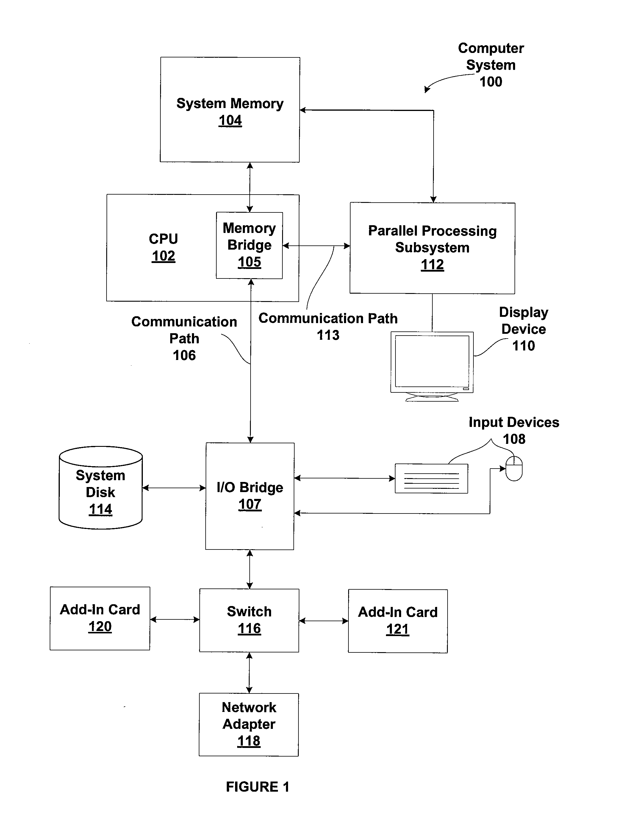
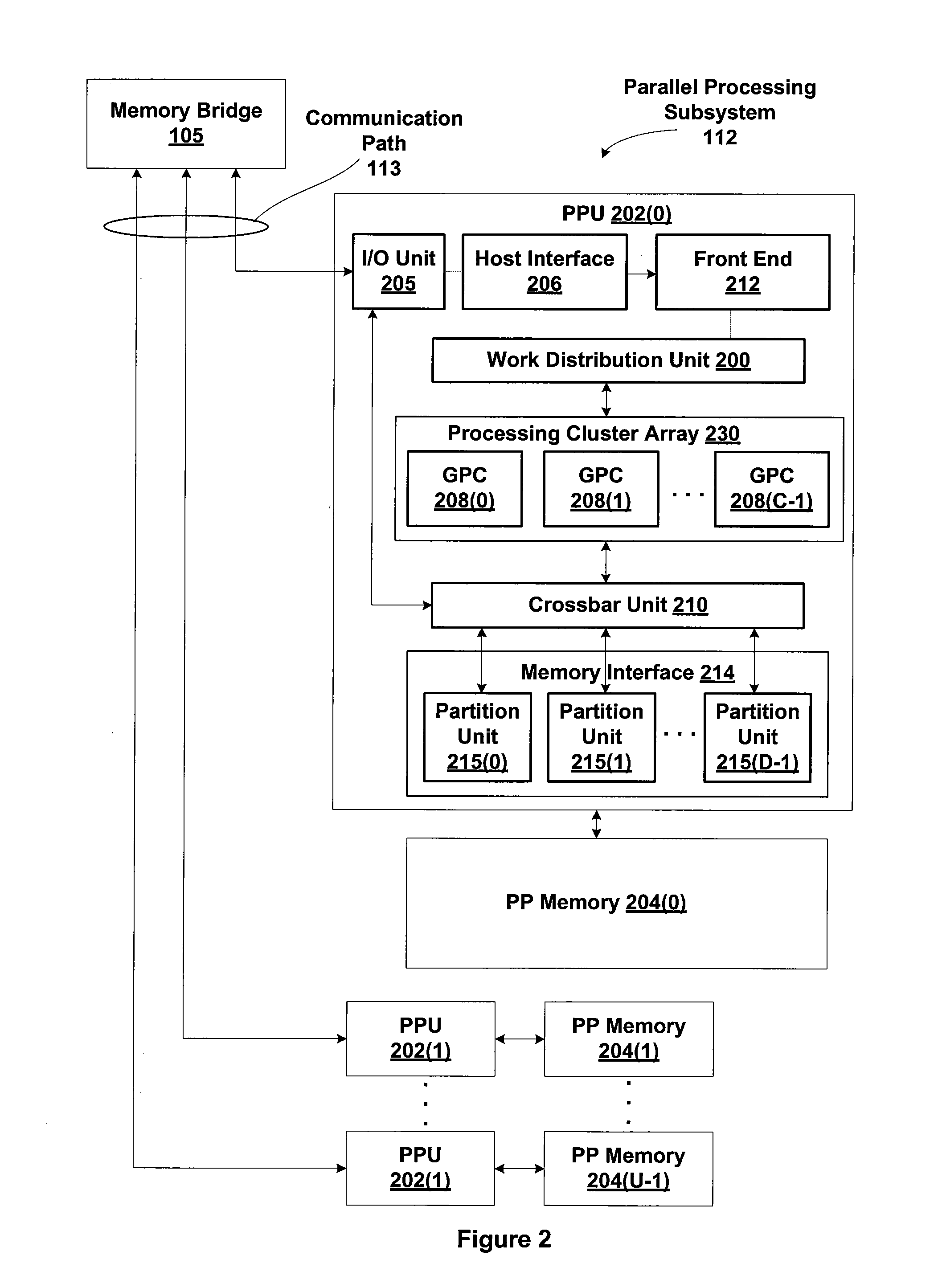
[0019]FIG. 1 is a block diagram illustrating a computer system 100 configured to implement one or more aspects of the present invention. Computer system 100 includes a central processing unit (CPU) 102 and a system memory 104 communicating via a bus path through a memory bridge 105. Memory bridge 105 may be integrated into CPU 102 as shown in FIG. 1. Alternatively, memory bridge 105, may be a conventional device, e.g., a Northbridge chip, that is connected via a bus to CPU 102. Memory bridge 105 is connected via communication path 106 (e.g., a HyperTransport link) to an I...
PUM
 Abstract
Description
Claims
Application Information