Method and apparatus for controlling bottom hole pressure in a subterranean formation during rig pump operation

a subterranean formation and bottom hole pressure technology, applied in the direction of survey, sealing/packing, borehole/well accessories, etc., can solve the problems of overbalanced technique, adversely affecting the permeability of the near borehole, and overbalanced drilling. , to achieve the effect of reducing the risk of rig failure, and reducing the safety of rig failur

Active Publication Date: 2013-07-23
MI +1
View PDF59 Cites 24 Cited by
  • Summary
  • Abstract
  • Description
  • Claims
  • Application Information

AI Technical Summary

Problems solved by technology

This overbalanced technique relies primarily on the fluid density and hydrostatic force generated by the column of fluid in the annulus to generate pressure.
However, the addition of weighting additives to increase fluid density (a) may not be rapid enough to deal with the formation fluid release and (b) may exceed the formation fracture pressure, resulting in the creation of fissures or fractures in the formation, with resultant fluid loss to the formation, possibly adversely affecting near borehole permeability.
The use of overbalanced drilling also affects the selection of casing during drilling operations.
Pressures in excess of the formation fracture pressure will result in the fluid pressurizing the formation walls to the extent that small cracks or fractures will open in the borehole wall and the fluid pressure overcomes the formation pressure with significant fluid invasion.
Fluid invasion can result in reduced permeability, adversely affecting formation production.
A gas kick in this interval may result in the pore pressure exceeding the annular pressure with a release of fluid and gas into the borehole, possibly requiring activation of the surface BOP stack.
As noted above, while additional weighting material may be added to the fluid, it will be generally ineffective in dealing with a gas kick due to the time required to increase the fluid density as seen in the borehole.
Fluid circulation itself also creates problems in an open system.
It will be appreciated that these spikes can cause fatigue on the borehole cake and could result in formation fluids entering the borehole, again leading to a well control event.
Moreover, it will be appreciated that where underbalanced systems are used, a significant well event will require that the BOPs be closed to handle the kick or other sudden pressure increase.

Method used


Image

  • Method and apparatus for controlling bottom hole pressure in a subterranean formation during rig pump operation
  • Method and apparatus for controlling bottom hole pressure in a subterranean formation during rig pump operation
  • Method and apparatus for controlling bottom hole pressure in a subterranean formation during rig pump operation

Examples


Embodiment Construction

[0021]In one aspect, embodiments disclosed herein relate to a method for maintaining pressure in a wellbore during drilling operations. As used herein, the term “drilling operations” includes all operations or activities that take place at the drilling site in connection with drilling a well, including, but not restricted to, the actual act of turning the drill string to cause a rotary drill bit to drill into the formation and including pumping the drilling mud, operating the draw works, the generation of electric power, the running of machinery, all other activities connected with operating a drilling site.

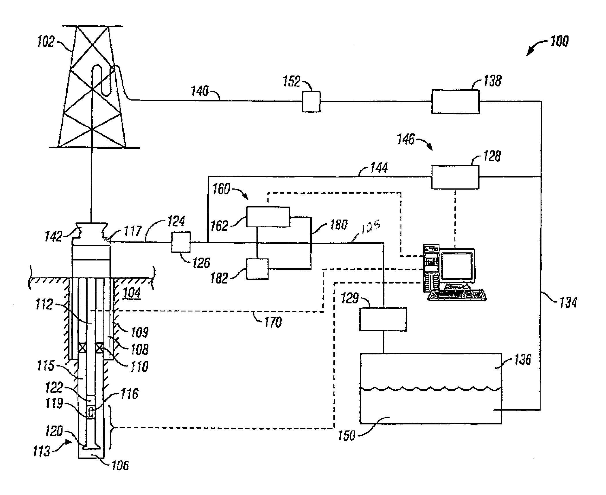
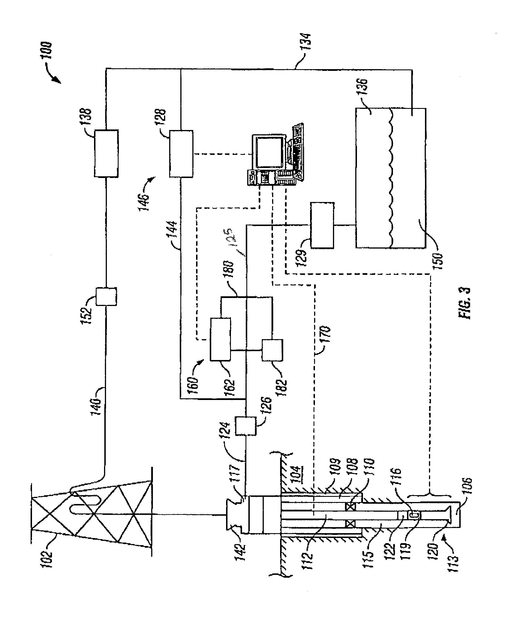
[0022]Referring to FIG. 3, an embodiment of an apparatus for maintaining pressure in a wellbore during drilling operations is shown. While FIG. 3 is a plan view depicting a surface drilling system employing the current invention, it will be appreciated that an offshore drilling system may likewise employ the current invention. The drilling system 100 is shown as being comprised o...


PUM


Abstract

A method for maintaining pressure in a wellbore during drilling operations includes the steps of providing fluid from a reservoir through a drill string, circulating the fluid from the drill string to an annulus between the drill string and the wellbore, isolating pressure in the annulus, measuring pressure in the annulus, calculating a set point backpressure, applying back pressure to the annulus based on the set point back pressure, diverting fluid from the annulus to a controllable choke, controllably bleeding off pressurized fluid from the annulus, separating solids from the fluid, and directing the fluid back to the reservoir. An apparatus for maintaining pressure in a wellbore during drilling operations includes an adjustable choke for controllably bleeding off pressurized fluid from the wellbore annulus, a backpressure pump for applying a calculated set point backpressure, and a processor for controlling the adjustable choke and backpressure pump.

Description

[0001]This application is the National Stage of International Application No. PCT / US07 / 82245, filed Oct. 23, 2007, which claims the benefit under 35 U.S.C. §119(e) of U.S. Provisional Application No. 60 / 862,558, filed Oct. 23, 2006.BACKGROUND OF INVENTION[0002]The exploration and production of hydrocarbons from subsurface formations ultimately requires a method to reach and extract the hydrocarbons from the formation. Referring to FIG. 1, a typical oil or gas well 10 includes a borehole 12 that traverses a subterranean formation 14 and includes a wellbore casing 16. During operation of the well 10, a drill pipe 18 may be positioned within the borehole 12 in order to inject fluids such as, for example, drilling mud into the wellbore. As will be recognized by persons having ordinary skill in the art, the end of the drill pipe 18 may include a drill bit and the injected drilling mud may be used to cool the drill bit and remove particles drilled away by the drill bit. The fluid then cir...

Claims


Application Information

Patent Timeline
Patent Type & Authority Patents(United States)
IPC IPC(8): E21B21/08E21B47/06
CPCE21B21/08
Inventor DUHE, JASONMAY, JAMES
Owner MI
Why Eureka
Try Eureka