Supercharge Your Innovation With Domain-Expert AI Agents!

Drive circuit with a transmission circuit for capacitively transmitting a signal and associated method

a transmission circuit and capacitative transmission technology, applied in the direction of multiple-port active networks, electrical equipment, electrical pulse generators, etc., can solve the problems of high cost of soi substrate wafers, and high cost of production

Active Publication Date: 2013-07-23
SEMIKRON ELECTRONICS GMBH & CO KG
View PDF6 Cites 6 Cited by
  • Summary
  • Abstract
  • Description
  • Claims
  • Application Information

AI Technical Summary

Benefits of technology

The invention is a circuit and method that can handle positive and negative potential differences equally, without the need for a separate circuit to generate pulses. This results in a more efficient and effective design.

Problems solved by technology

In the case of relatively high intermediate circuit voltages, generally greater than 40 V, the drive logic unit is usually isolated in terms of potential from the driver circuits, since the associated power switches are at a different potential and voltage isolation is therefore unavoidable.
The SOI technology affords dielectric isolation of components and component groups, but is currently available only up to a dielectric strength of about 800 V. The SOI substrate wafers are significantly more expensive than standard substrates, although the costs are offset by a series of technical advantages and also considerable process simplifications which result from the dielectric isolation.
This technology is currently available up to about 1200 V. However, production thereof is very complicated and therefore cost-intensive.
Furthermore, there are technical problems, for example with leakage currents and latch-up effects, inter alia, at relatively high temperatures, for example at an operating temperature of more than about 125° C., and also in the event of chopping of the ground potential during fast dynamic operations.
The most significant disadvantage of the method is the required generation of the switch-on and switch-off pulses.
This results in increased circuit complexity and space requirement and thus higher costs.
Internal inductances of a system comprising a power semiconductor module and a drive circuit, for example line inductances, may result in severe chopping of the reference potential of the BOT secondary side in a positive or negative direction during switching of the power switches.
Severe chopping of the reference potential of the TOP secondary side below the reference potential on the drive side may likewise result.
The known pn isolation technologies have the disadvantage that the triggering of parasitic thyristor structures, so-called latch-up, can occur in the event of corresponding chopping of the reference potential in the negative direction.
This leads to loss of function and possibly to destruction of the affected transistors.
This limitation is not manifested in SOI technologies, due to the dielectric isolation of the components, with the result that it is possible to implement, using circuit technology, a level shifter which ensures reliable signal transmission even in the case of a secondary-side reference potential which is briefly or permanently negative.

Method used


Image

  • Drive circuit with a transmission circuit for capacitively transmitting a signal and associated method
  • Drive circuit with a transmission circuit for capacitively transmitting a signal and associated method
  • Drive circuit with a transmission circuit for capacitively transmitting a signal and associated method

Examples


Embodiment Construction

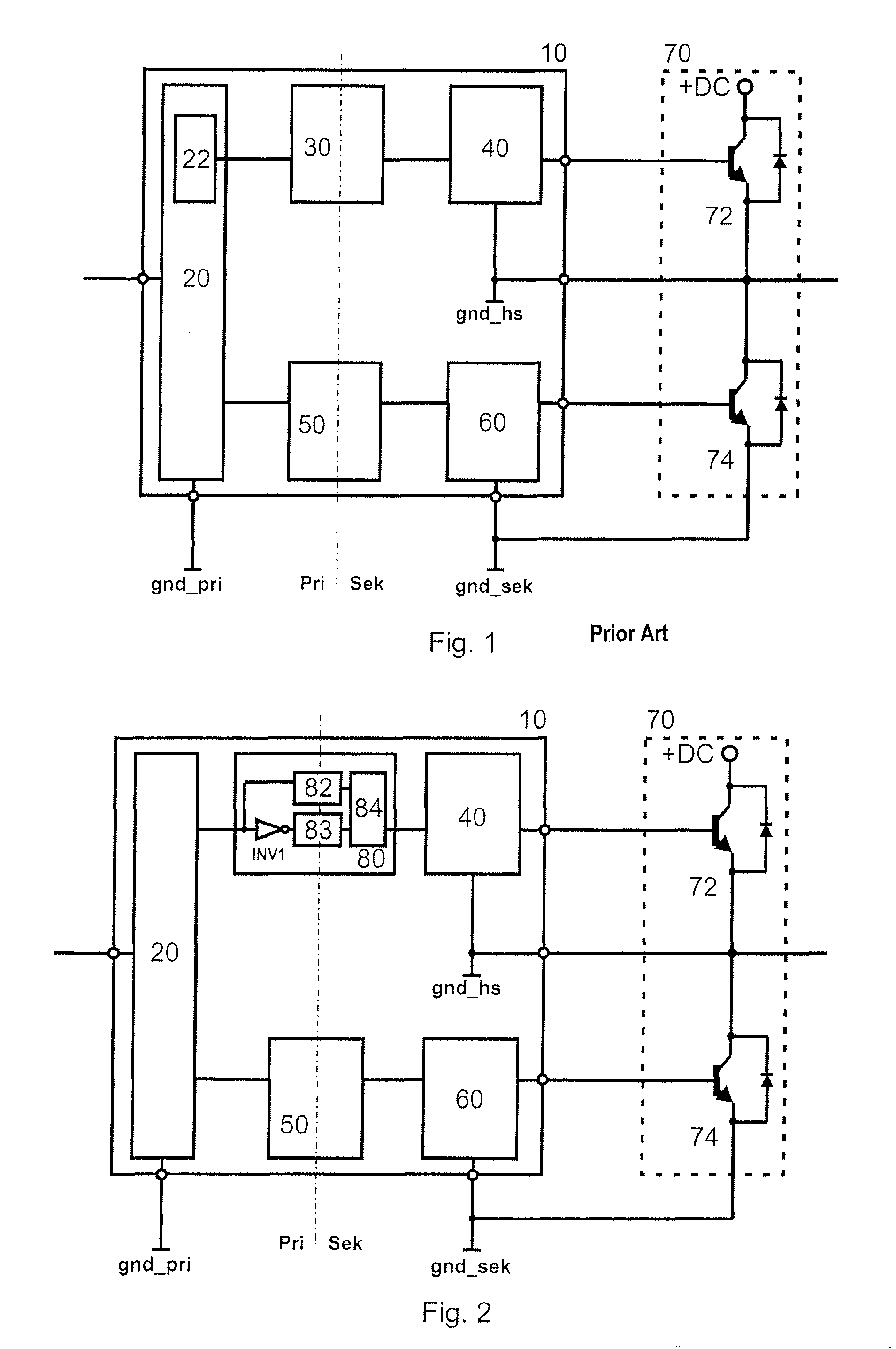
[0030]To explain the invention, FIG. 1 shows a block diagram having a monolithically integrated drive circuit 10 according to the prior art as well as a half-bridge circuit 70 which can be driven thereby. Half-bridge circuit 70 has a TOP power switch 72 and a BOT power switch 74 which in this case are each in the form of an IGBT with a diode reverse-connected in parallel. The BOT power switch 74 is at the reference potential (gnd_sek) of the secondary side, which, in applications having small line inductances, is virtually equal to the reference potential (gnd_pri) of the primary side of the drive circuit 10.

[0031]Drive circuit 10 itself has a drive logic unit 20 with a necessary pulse generation circuit 22, a first UP transformer 30 with a downstream TOP secondary side 40, and a second UP transformer 50 with a downstream BOT secondary side 60, in which case the respective UP transformers are in the form of level shifters according to the prior art.

[0032]FIG. 2 shows a block diagram...


PUM


Abstract

A drive circuit with a circuit for transmitting a signal from a primary side having a first ground to a secondary side having a second ground. The transformer has capacitive coupling between the primary and secondary sides. The transformer has an ON transmission branch and an OFF transmission branch, which each have a first partial branch and a second partial branch. Capacitive coupling between the primary and secondary sides is effected in each partial branch by high-voltage capacitors. In the inventive method, in each transmission branch, the signal generates a current flow through a first HV capacitor of a first partial branch and an inverse current flow through a second HV capacitor of a second partial branch. This respective current flow is detected on the secondary side and is supplied to an evaluation circuit common to the two partial branches and reconstructs the primary-side input signal on the secondary side.

Description

BACKGROUND OF THE INVENTION[0001]1. Field of the Invention[0002]The invention is directed to a monolithically integratable drive circuit with transmission circuits and an associated method for operating such a drive circuit to transmit an input signal such as from a drive logic unit to a driver.[0003]2. Description of the Related Art[0004]Drive circuits such as described herein are needed in power electronic systems to drive power semiconductor switches which are arranged as individual switches or in a bridge circuit. Such bridge circuits are known as single-phase, two-phase or three-phase bridge circuits in the form of power semiconductor modules. The single-phase so-called half-bridge constitutes the basic module of a multiplicity of power electronic circuits. In a half-bridge circuit, two power switches, a first so-called TOP switch and a second so-called BOT switch, are arranged in series.[0005]Such a half-bridge generally has a connection to a DC intermediate circuit. The outpu...

Claims


Application Information

Patent Timeline
Patent Type & Authority Patents(United States)
IPC IPC(8): H03B1/00H03K3/00
CPCH03K17/689H01L2924/0002H01L2924/00
Inventor VOGLER, BASTIANHERZER, REINHARDROSSBERG, MATTHIAS
Owner SEMIKRON ELECTRONICS GMBH & CO KG
Features
  • R&D
  • Intellectual Property
  • Life Sciences
  • Materials
  • Tech Scout
  • Unparalleled Data Quality
  • Higher Quality Content
  • 60% Fewer Hallucinations
Learn More