Wireless sensor reader

a sensor reader and wireless sensor technology, applied in the field of wireless sensor readers, can solve the problems of poor resolution, abandonment, and many deficiencies of current passive sensor readers, such as those disclosed above, and achieve the effect of improving the accuracy of reading results

Active Publication Date: 2013-07-23
ENDOTRONIX
View PDF178 Cites 61 Cited by
  • Summary
  • Abstract
  • Description
  • Claims
  • Application Information

AI Technical Summary

Benefits of technology

[0028]FIG. 15 is a block diagram depicting an alternate embodiment of the timing and control circuitry of FIG. 8, in which t

Problems solved by technology

Current designs for passive sensor readers, such as those disclosed above, suffer from a number of deficiencies.
2, April 1967) discloses that these systems suffered from inaccuracy and poor resolution due to difficulties in measuring the short-lived ring signal frequency, leading to their abandonment in favor of various swept-frequency methods.
This limits other uses of the spectrum and makes interference a potential issue.
Readers that track the resonant frequency of a passive resonant sensor with a variable frequency transmitter, such as Genest, Ellis

Method used


Image

  • Wireless sensor reader
  • Wireless sensor reader
  • Wireless sensor reader

Examples


Embodiment Construction

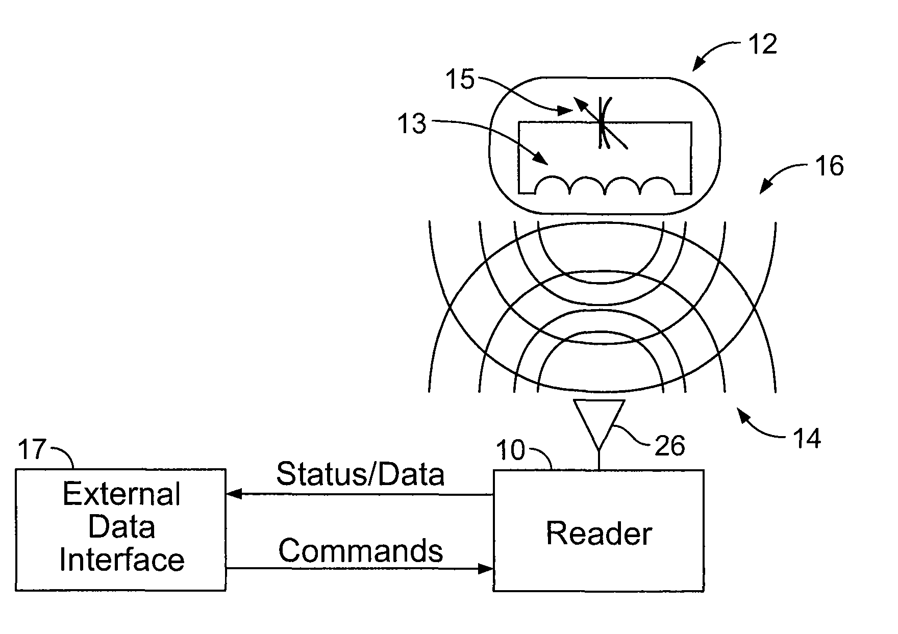
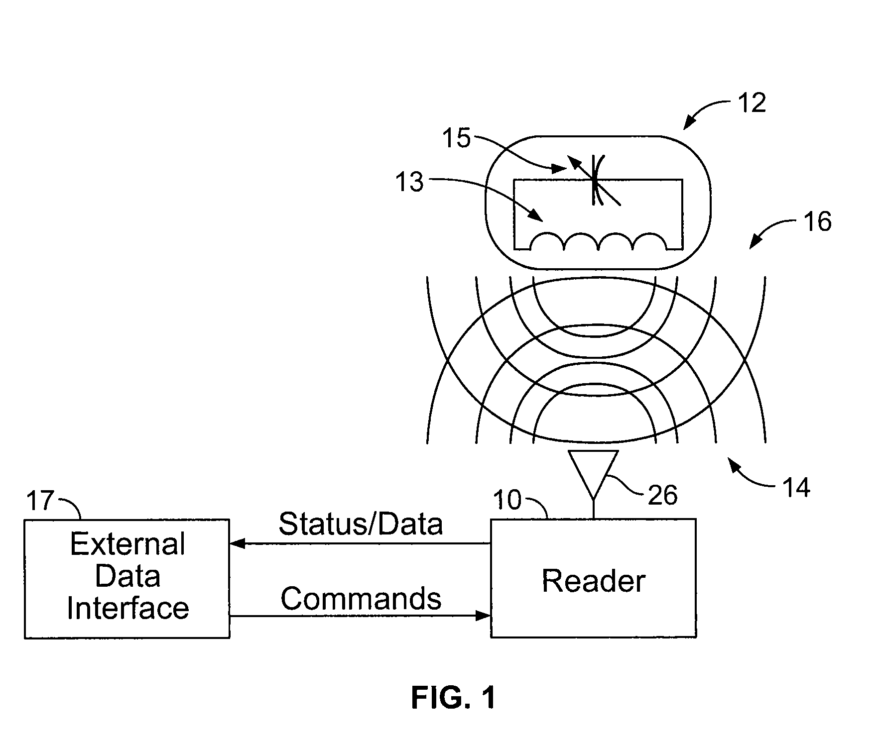
[0032]A passive wireless sensor system including a reader 10 in remote communication with a sensor 12 is provided. The reader 10 is capable of exciting the sensor 12 by transmitting a signal, such as a radio frequency (“RF”) pulse, at or near the resonant frequency of the sensor 12. (See FIG. 1.) The sensor 12 may emit a ring signal for a short period of time in response to the excitation pulse from the reader 10.

[0033]The sensor 12 may be a passive device, containing no power source of its own, and capable of emitting a ring signal 16 in response to an excitation signal 14 at or near the resonant frequency of the sensor 12. The sensor 12 may be configured to sense a specific parameter. For example, the sensor 12 may include a fixed inductor 13 and a capacitor 15 that varies based on the sensed parameter. The varying capacitance or inductance alters the resonant frequency of the sensor 12. It should be appreciated, however, that the sensor 12 may be any wireless sensor known in the ...


PUM


Abstract

A wireless sensor reader is provided to interface with a wireless sensor. The wireless sensor reader transmits a narrowband, fixed frequency excitation pulse to cause the wireless sensor to generate a ring signal. The ring signal corresponds to the value of the physical parameter being sensed. The wireless sensor reader receives and amplifies the ring signal and sends the signal to a phase-locked loop. A voltage-controlled oscillator in the phase-locked loop locks onto the ring signal frequency and generates a count signal at a frequency related to the ring signal frequency. The voltage-controlled oscillator is placed into a hold mode where the control voltage is maintained constant to allow the count signal frequency to be determined. The low power, simple circuitry required to generate the excitation pulse allows the reader to be a small, battery operated unit. Alternative methods of frequency determination are also disclosed.

Description

RELATED APPLICATIONS[0001]This non-provisional application is a continuation-in-part of U.S. patent application Ser. No. 12 / 419,326 filed on Apr. 7, 2009 which is a continuation-in-part of U.S. patent application Ser. No. 12 / 075,858 filed on Mar. 14, 2008, which claims priority to U.S. Provisional Application No. 60 / 918,164 filed on Mar. 15, 2007, each of which is hereby incorporated by reference.TECHNICAL FIELD[0002]This invention relates generally to reading passive wireless sensors, and more particularly to a reader circuitry and a method for exciting and sensing data from passive wireless sensors.BACKGROUND[0003]Passive wireless sensor systems that employ resonant circuit technology are known. These systems utilize a passive wireless sensor in remote communication with excitation and reader circuitry. Often the wireless sensor is implanted at a specific location, such as within the human body, to detect and report a sensed parameter. The sensed parameter varies the resonant circ...

Claims


Application Information

Patent Timeline
IPC IPC(8): H04Q5/22
CPCA61B5/0031A61B5/0215A61B5/6882A61B5/726A61B2562/0219
Inventor ROWLAND, HARRY D.WALKING, ROGER DWIGHTSUNDARAM, BALAMURUGANPAUL, BRYANAHN, IN SOONAGY, MICHAEL
Owner ENDOTRONIX
Why Eureka
Try Eureka