System and method for programming oscillators

a programming oscillator and programming system technology, applied in the field of system and method programming oscillators, can solve the problems of loss of yield, increased phase noise and jitter, and failure of plating adhesion, so as to reduce oscillator programming control costs, simplify design, and achieve greater degree of freedom

Inactive Publication Date: 2002-10-17
CARDINAL COMPONENTS INC
View PDF0 Cites 16 Cited by
  • Summary
  • Abstract
  • Description
  • Claims
  • Application Information

AI Technical Summary

Benefits of technology

0073] It is another object of the invention to provide a system and method for programming a programmable oscillator having a nonvolatile memory for persistently storing a control algorithm and a tuning control, wherein the tuning effect is determined before programming of nonvolatile memory with the control algorithm. Therefore, the control algorithm is constrained only by a set of available parameters while determining the tuning control, allowing great

Problems solved by technology

Not only the thickness, but also the placement of the plating is critical; if it is not exactly concentric over the pre-plate region, phase noise and jitter are increased.
The final plate process also results in loss of yield.
For example, there is a probability of plating adhesion failure.
Thus, the final plate process is expensive, labor consuming, reduces crystal quality, and potentially induces defects.
In this case, the oscillators are not field programmable, and an

Method used


Image

  • System and method for programming oscillators
  • System and method for programming oscillators
  • System and method for programming oscillators

Examples


example 2

TCVCDCXO

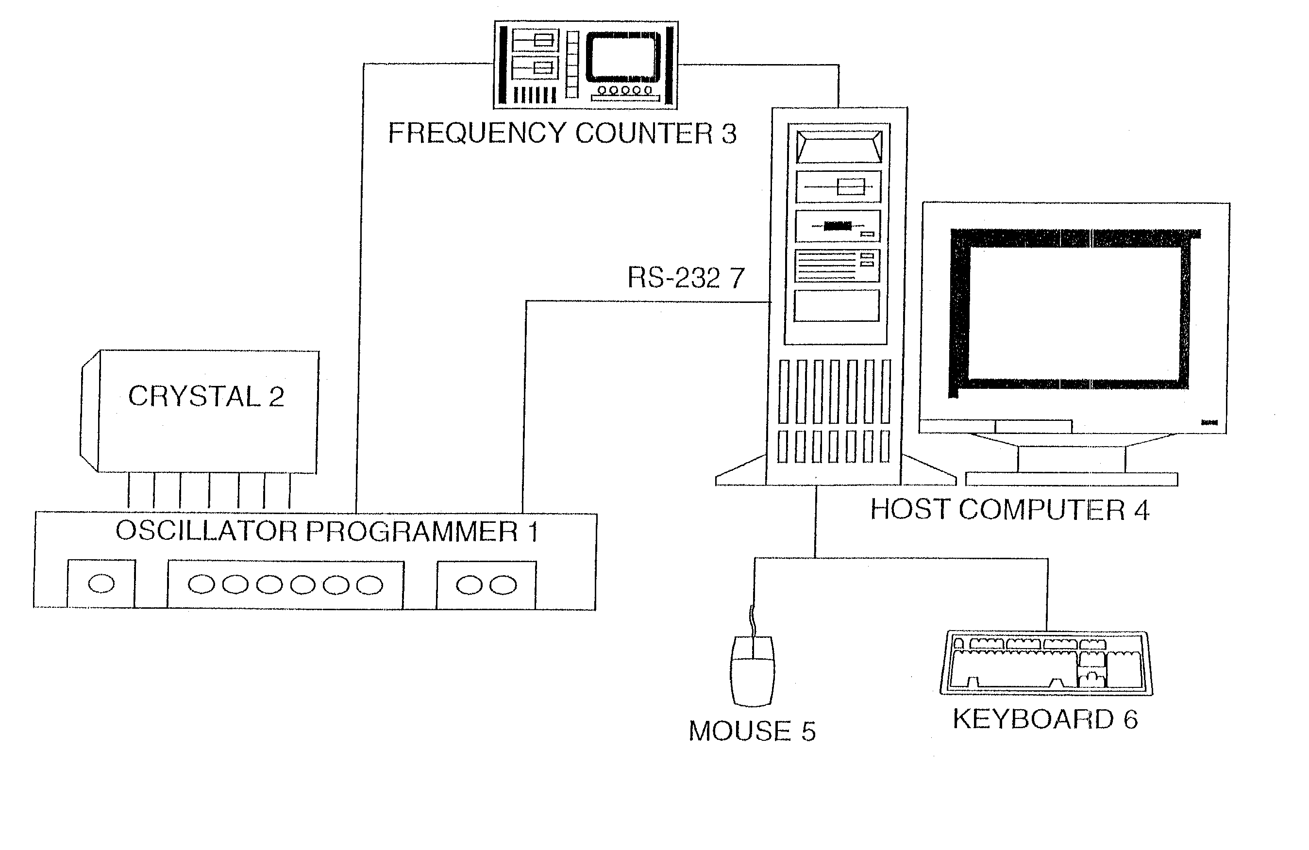
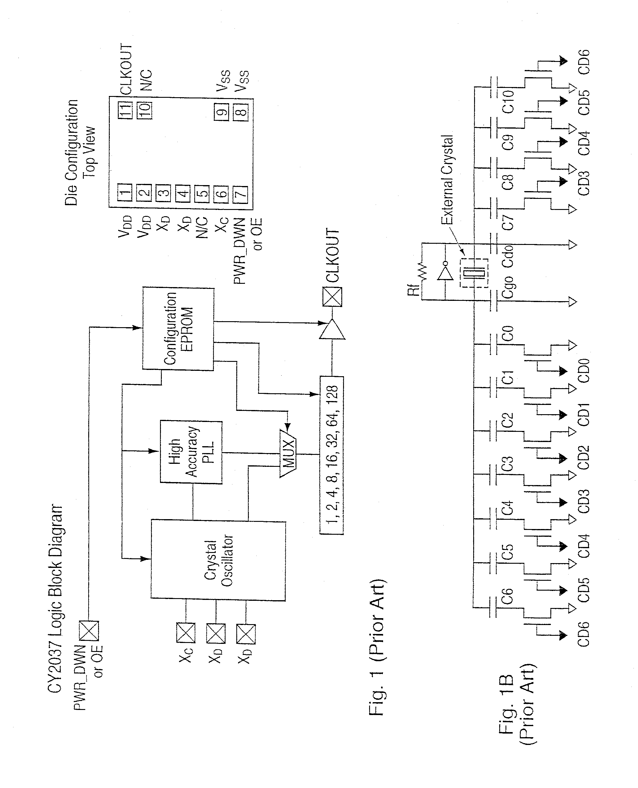
[0110] The circuit of Example 1 is modified by substituting the output of an MAS1175 oscillator, shown in FIG. 8, for the crystal in the circuit of FIG. 1B, with the output of the MAS1175 connected to the input X.sub.G of the CY2037. Therefore, the tuning capacitor network of the CY2037 will be ineffective, and thus need not be present. The programming device shown in FIG. 5 is used, with a different oscillator programmer 1 personality module, shown in more detail in FIGS. 6A and 6B, designed for this part. In particular, the circuit of FIG. 6B additionally handles the clock, data, and programming input pins of the MAS1175. These signals (along with possibly other test and diagnostic signals) may be brought to pins on the oscillator package.

[0111] The programming method incorporates the initial CY2037 programming steps shown in FIG. 7A and the selection of operating and oscillator trimming values as shown in FIG. 7B, with the possible exception of the selection of test trimm...

example 3

[0118] FIG. 10A shows a prior art packaged oscillator having an external power supply bypass capacitor. Typically, packaged PLL oscillators has relied on external bypass capacitors. Some known non-PLL oscillators have included internal bypass capacitors, in larger package sizes. FIG. 10B shows a packaged PLL oscillator having an internal power supply bypass capacitor according to the present invention. According to this embodiment, a 10-100 nF chip capacitor is provided within the oscillator housing for power supply bypassing.

[0119] FIGS. 11A and 11B, and 11C and 11D shows, respectively, comparative tracings of the jitter distributions between the comparative example of FIG. 10A and the example of FIG. 10B for 100 MHz (FIGS. 11A and 11B) and 40 MHz (FIGS. 11C and 11D) PLL oscillators, respectively. In each case, the non-bypassed oscillator displays a bimodal (or in some cases, not shown, a trimodal distribution), while the PLL oscillators with internal bypass capacitors have lower o...


PUM


Abstract

A system and method for programming a digitally tunable oscillator is provided. A desired output frequency is received. A tuning effect of a set of digital tuning words on a crystal resonant frequency is determined, and valid parameters of an algorithm for translating and tuning the crystal resonant frequency to a value within an error tolerance of the desired frequency, based on the determined tuning effect are calculated. Valid parameters are preferably calculated based on an intermediate tuning value, sorted by ascending divide parameter of the algorithm, and then evaluated in sorted order for ability of a tuning effect to null frequency error to within the error tolerance. The valid set of calculated parameters are then programmed into a nonvolatile memory. The oscillator control parameters may remain unprogrammed until all necessary parameters are defined. Because the device may be programmed in a single step, without intermediate presumption of nominal crystal frequency, the final plate process may be unnecessary. A high accuracy may be obtained by searching through the complete set of available parameters for a set that meets a frequency and tolerance specification. The oscillator is preferably a Cypress CY2037 device alone or in combination with a Micro Analog Systems MAS1175 device.

Description

[0001] The present invention relates to the field of programmable oscillators, and more particularly to systems and methods including high accuracy EPROM programmable phase locked loop oscillators.[0002] The CY2037 from Cypress Semiconductor Corporation (San Jose, Calif.), is an EPROM-programmable (electrically programmable read only memory), high-accuracy and resolution, PLL-based (phase-locked loop) digitally controlled crystal oscillator (DCXO). The device has a low jitter specification, e.g., <.+-.100 ps (pk-pk) at 5 V and f>33 MHz and<.+-.125 ps (pk-pk) at 3.3 V and f>33 MHz. The device is available die form, i.e., without packaging, and attaches directly to a 10-30 MHz crystal. The oscillator device may be packaged into various through-hole or surface mount packages. A block diagram of this circuit is shown in FIG. 1A.[0003] Traditionally, an oscillator crystal is calibrated in an operation termed the "final plate", from an initial accuracy of within 2,000-3,000 pp...

Claims


Application Information

Patent Timeline
IPC IPC(8): H03L1/02H03L7/18
CPCH03L7/18H03L1/025
Inventor BABCOCK, DAVID J.
Owner CARDINAL COMPONENTS INC
Why Eureka
Try Eureka