Inverter circuit having relatively higher efficiency

a technology of inverter circuit and efficiency, which is applied in the direction of ac-dc conversion, power conversion system, electrical apparatus, etc., can solve the problems of reducing efficiency, excessive costs, and generating electric power, and achieves the effect of increasing efficiency, reducing total volume and total cost of inverter circuit, and increasing efficiency

Active Publication Date: 2013-07-23
DELTA ELECTRONICS INC
View PDF5 Cites 5 Cited by
  • Summary
  • Abstract
  • Description
  • Claims
  • Application Information

AI Technical Summary

Benefits of technology

[0004]It is therefore an object of the present invention to provide an inverter circuit having a relatively higher efficiency. When a PWM switch of the inverter circuit is turned off, there is an independent diode being employed to realize the freewheeling current instead of a body diode inside the PWM switch such that the efficiency of the inverter circuit is increased. And through employing three inductors with relatively smaller inductances, both the total volume and the total cost of the inverter circuit are decreased.
[0014]Preferably, the circuit further comprises a third inductor having a first terminal coupled to the second terminal of the second inductor and a second terminal outputting the AC voltage, wherein each of the first to the third inductors has an inductance, the inductance of the third inductor is larger than both of the respective inductances of the first and the second inductors, the first and the second switches have a first and a second body diodes respectively, the inductance of the first inductor has a lower limit set to prevent from a turn-on of the second body diode when the first switch is turned off and the inductance of the second inductor has a lower limit set to prevent from a turn-on of the first body diode when the second switch is turned off.

Problems solved by technology

Although being developed for many years, there are still drawbacks currently in employing solar cell to generate the electric power such as excessive costs and lower efficiency. FIG. 1 shows a schematic circuit diagram of a conventional non-isolated inverter circuit.
If IGBTs are employed, the turn-on losses of which are quite large since the turn-on voltage drop is pretty high, usually exceeding 2V, that will cause the lower efficiency of the inverter employing the IGBT, and the efficiency is lower than 97% according to the existing technologies.
The current flows through S1-L1-L3 when S1 is turned on and the current flows through the body diode of S2-L1-S3 when S1 is turned off, results in quite large loss due to the poor characteristic of the body diode of S2, and is disadvantageous to the increase of the efficiency.
When the AC output voltage VG is in the negative-half cycle and is negative, S4 is constantly turned on and there is also a stage of freewheeling current of the body diode of S1 while S2 is used as a PWM switch, and also results in a great deal of loss.

Method used


Image

  • Inverter circuit having relatively higher efficiency
  • Inverter circuit having relatively higher efficiency
  • Inverter circuit having relatively higher efficiency

Examples


Embodiment Construction

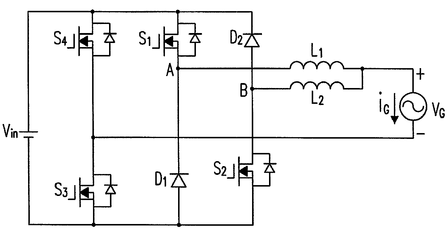
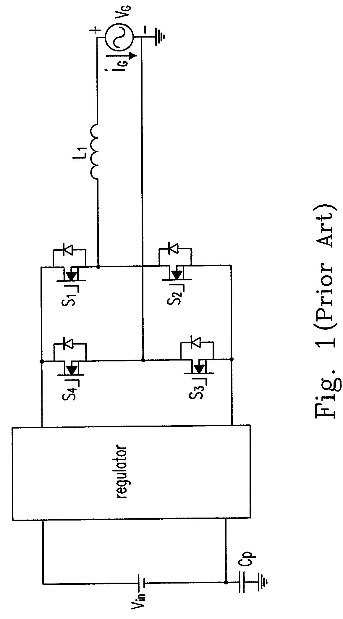
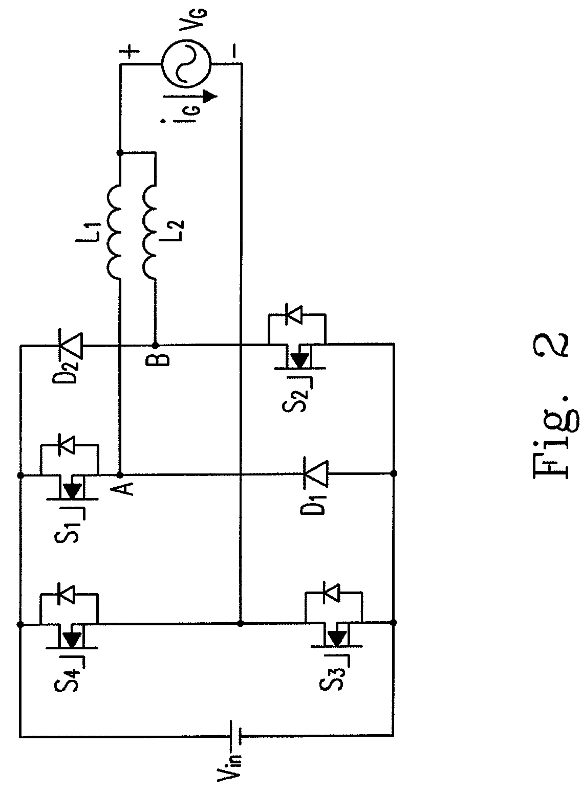
[0029]The first preferred embodiment of the present invention is shown in FIG. 2. FIG. 2 shows a circuit diagram of an inverter circuit according to the first preferred embodiment of the present invention. The differences between FIG. 2 and FIG. 1 are that a first diode D1, a second diode D2 and a second inductor L2 are added. In FIG. 2, the switch S1 and the diode D1 are coupled to a first middle point A, the switch S2 and the diode D2 are coupled to a second middle point B, the third switch S3 and the fourth switch S4 are coupled to a third middle point, the first terminals of the inductors L1 and L2 are coupled to the first and the second middle points respectively, the second terminals of the inductors L1 and L2 are commonly coupled to an output terminal, and the output terminal and the third middle point are both used for outputting the AC voltage VG. S1 and S2 could be CoolMOS devices having a rated voltage of 650V, D1 and D2 could be diodes having a rated voltage of 600V, and...


PUM


Abstract

The configurations of an inverter circuit are provided in the present invention. The proposed circuit includes a first bridge arm having a first sub-bridge arm with a first switch and a first middle point coupled to the first switch, and a second sub-bridge arm with a second switch and a second middle point coupled to the second switch, a first inductor having a first terminal coupled to the first middle point and a second terminal, and a second inductor having a first terminal coupled to the second middle point, and a second terminal coupled to the second terminal of the first inductor and outputting an AC voltage.

Description

FIELD OF THE INVENTION[0001]The present invention relates to an inverter circuit with a relatively higher efficiency. More particularly, the present invention relates to an inverter circuit with a relatively higher efficiency and being applied to power systems of renewable energy (such as wind energy, solar energy and so on).BACKGROUND OF THE INVENTION[0002]Following the excessive consumption of the mineral fuels such as the petroleum and natural gas, the prices of fuels are continuously increased, and the influences towards the environment caused by the excessive consumption of the mineral fuels are more and more significantly at the same time. To meet the economy and environmental protection requirements, the alternative energy sources are sought globally, and employing the renewable energy (such as wind energy, solar energy and so on) to generate the electric power is the most important development direction. Although being developed for many years, there are still drawbacks curr...

Claims


Application Information

Patent Timeline
Patent Type & Authority Patents(United States)
IPC IPC(8): H02M7/5387
CPCH02M7/5387H02M1/0085
Inventor TAN, JINGTAOYI, DEGANGLV, FEILEE, LEI-MINGYING, JIANPINGTSAI, WEN-YIN
Owner DELTA ELECTRONICS INC
Why Eureka
Try Eureka