Generating a regularly synchronised count value

a count value and count value technology, applied in the field of counters, can solve the problems of difficult to provide a timestamp that is consistent across the system, and the high frequency clock will clearly consume significant power, so as to achieve high resolution count, increase power consumption, and high resolution count value

Active Publication Date: 2013-07-30
ARM LTD
View PDF6 Cites 0 Cited by
  • Summary
  • Abstract
  • Description
  • Claims
  • Application Information

AI Technical Summary

Benefits of technology

[0016]One advantage of embodiments of the present invention is that as the interpolator determines the increment value from the frequency ratio and the saturated value of the counter then if either of the frequencies change the interpolator can simply calculate a new increment value and the count value generator can operate at this new frequency. Thus, either the local frequency or the synchronising frequency may change and the device can still operate correctly. This can be particularly useful in some systems where these frequencies vary depending on perhaps the power domain that the device is operating within.
[0022]In addition to determining a new increment value, a change in the synchronising frequency may trigger a change in the source of the number of higher order bits and lower order bits that are output as the output count value. Where for example the synchronising frequency increases then it may be suitable for the synchronising count value to generate some of the lower order bits of the output count value these bits previously being generated by the counter clocked by the local clock. While in response to said synchronising frequency decreasing a fewer number of higher order bits are generated from said synchronising count value and a greater number of bits are generated by said counter.
[0026]One use of the counter may be as a time stamp generator. It is often important that the relative time that an event occurred can be determined within a processing system. Where there are different clock signals operating at different frequencies it can be difficult to generate a time stamp without transmitting a fast frequency clock throughout the system which is expensive on power. Using counters of embodiments of the present invention that are synchronised to a slow frequency value which is sent throughout a system and yet which have the resolution of the local clock is a convenient and power efficient way of generating time stamps.
[0031]The counter may be designed in a number of ways. In some embodiments it is found to be convenient to add the increment value to the lower and lowest order bits using an adder and to simply increment by 1 the higher order bits using a signal triggered by an overflow from the lower order bits. Incrementing by 1 is a simple function to build electronically and thus, as the higher order bits will always change value by incrementing by 1 this is an efficient way of generating the circuitry required to control the counter.
[0033]A clock value generator according to embodiments of the present invention are particularly suitable for use with integrated circuits that have different clock domains. The transmission of a synchronising count value that increments at a slow clock frequency to different portions of the integrated circuit can be done relatively simply and in a power efficient manner. A locally generated higher resolution count value can then be provided by providing lower order bits generated from a local clock that is operating in a higher frequency domain. This makes use of the local clock and avoids the need to transmit high frequency clock signals throughout the system. Furthermore, the portions of the integrated circuit between the different domains may only operate at lower clock frequencies such that it may be difficult to transmit higher clock frequencies through these portions, or doing so may require the circuit to be redesigned to have portions that can operate at higher clock frequencies between the clocking domains which would again increase power consumption. The synchronising count value allows count values generated in the different clock domains to be related to each other while the use of the local clocks enables high resolution count values to be generated that can be synchronised with each other and yet do not require a high power to generate.

Problems solved by technology

However, as data processing systems get larger and have different clock frequency domains, and indeed domains that are clocked at frequencies that vary with time, it is difficult to provide a timestamp that is consistent across a system.
A further constraint associated with the provision of timestamp information is the power demands associated with such provision.
Timestamps that are generated for debug purposes for example, require a relatively high clock frequency in order to provide sufficiently high resolution, however as the time value is required to run continuously a high frequency clock will clearly consume significant power.

Method used


Image

  • Generating a regularly synchronised count value
  • Generating a regularly synchronised count value
  • Generating a regularly synchronised count value

Examples


Embodiment Construction

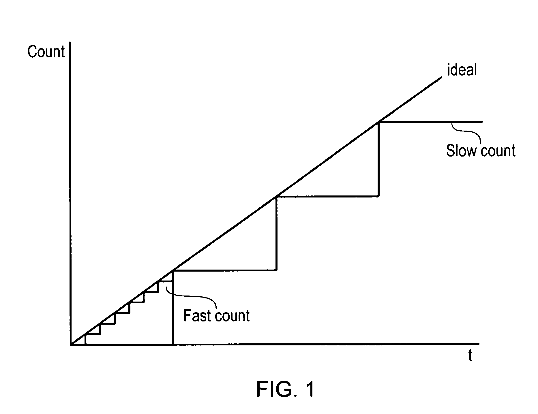
[0046]FIG. 1 shows schematically how a count value varies with time when it increments at a slow frequency the large step showing a slow count, or when it increments at a faster frequency the smaller steps illustrated a fast count. As can be seen the fast count steps follow the “ideal” line more closely and if they are being used to provide an estimate of time provide a more accurate idea of current time than the slower count steps.

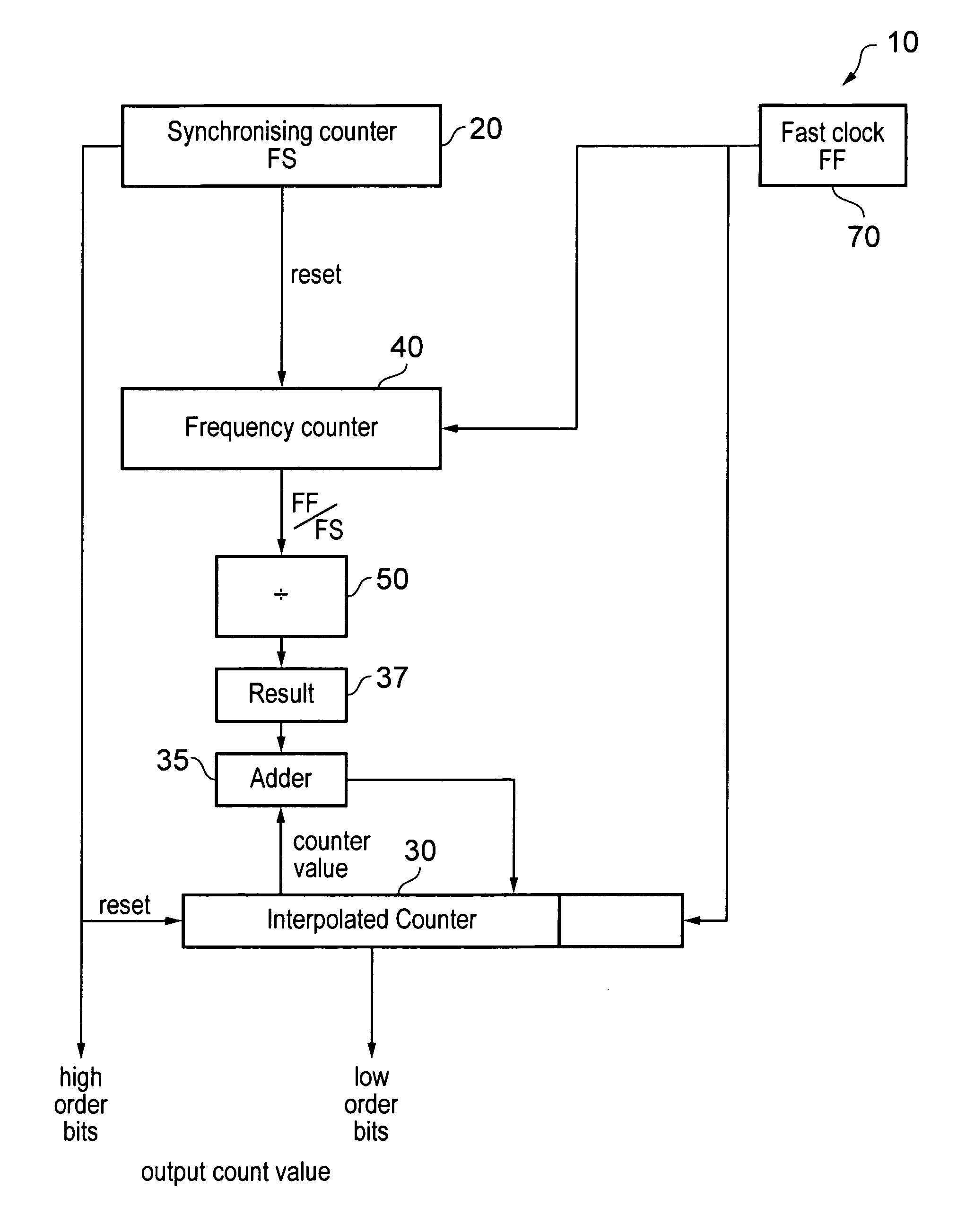
[0047]Embodiment of the current invention are concerned with using a faster clock to provide the smaller steps by generating the lower order bits of a count value and thereby providing a count value with higher resolution, while generating the higher order bits of a count value from a slower count value. The slower count value can be used as a synchronising count value where different fast clocks can be used to provide intermediate steps which are synchronised by the slower stepped slow count value.

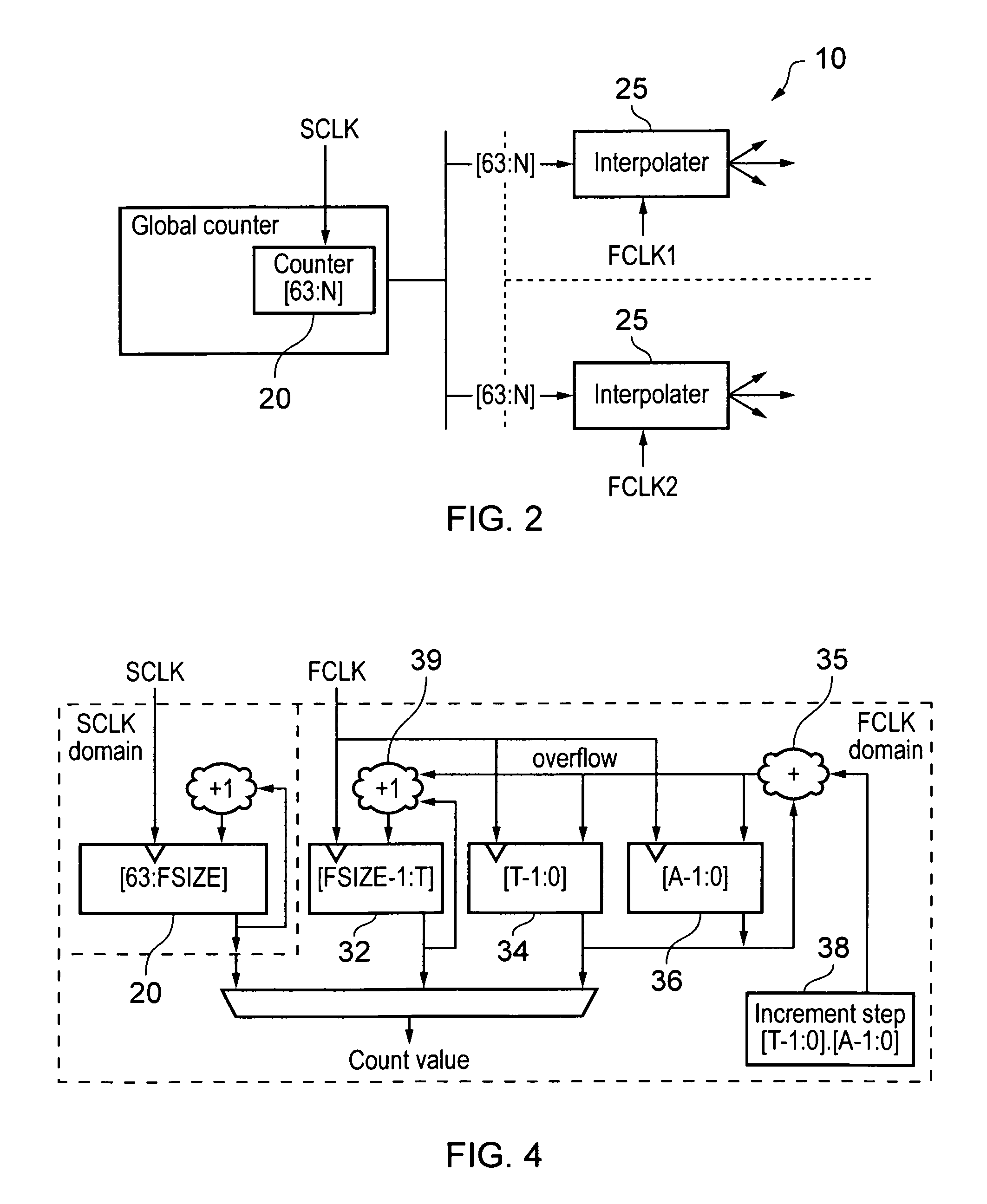
[0048]FIG. 2 shows schematically a circuit 10 for generat...


PUM


Abstract

A count value generator includes an input for receiving a synchronizing count value, a counter configured to increment at a local frequency, the local frequency being faster than the synchronizing frequency, and an interpolator for determining a frequency ratio between the local frequency and the synchronizing frequency and for determining an increment value for the counter dependent on a relative amount of a maximum value of the counter with respect to the frequency ratio is disclosed. The counter generates a count value including a predetermined number of bits representing integer values and output as the lower order bits of the output count value and additional lower order bits that represent fractional portions of the integer values. The counter includes output circuitry for outputting the synchronizing count value and the predetermined number of bits representing integer values generated by the counter as the lower order bits of the count value.

Description

BACKGROUND OF THE INVENTION[0001]1. Field of the Invention[0002]This application claims priority to Indian Application No. 2727 / DEL / 2011 filed 20 Sep. 2011, the entire contents of which are incorporated herein by reference.[0003]The field of the invention relates to counters and in particular to generating a count value from a slow incrementing counter and a faster clock signal.[0004]2. Description of the Prior Art[0005]Counters that provide count values that increment in response to a clock signal are known. These count values can be used as an indication of a current time provided that the clock signal driving the counter has a constant frequency that is known.[0006]In data processing systems it is often useful, for example when diagnosing a system, to know the relative time that certain events happened with respect to other events. In order to be able to determine this count values that are used as timestamps can be added to various transactions as they pass through a data proces...

Claims


Application Information

Patent Timeline
Patent Type & Authority Patents(United States)
IPC IPC(8): H03L7/00
CPCG04F10/04G06F1/14
Inventor HORLEY, JOHN MICHAELWOODHOUSE, SHELDON JAMESWILLIAMS, MICHAEL JOHNKALKUNTE, SHESHADRIROSE, ANDREW CHRISTOPHER
Owner ARM LTD
Why Eureka
Try Eureka