Electrode unit joining structure for superconducting wire, superconducting wire, and superconducting coil

a superconducting wire and electrode unit technology, applied in the direction of superconducting magnets/coils, magnetic bodies, connection contact material materials, etc., can solve the problems of high cooling cost, inability to use conductors, and inability to maintain a superconducting state of metal-based superconductors, so as to prevent the burning out of the superconducting wire, reduce the joule heat that occurs due to the contact resistance between the electrode and the superconducting

Active Publication Date: 2013-07-30
FUJIKURA LTD
View PDF9 Cites 0 Cited by
  • Summary
  • Abstract
  • Description
  • Claims
  • Application Information

AI Technical Summary

Benefits of technology

[0019]According to the electrode unit joining structure for a superconducting wire according to the aspect of the invention, the electrode unit joining structure for a superconducting wire is configured in such a manner that the superconducting cover tape is provided so as to cover a top surface of the electrode that is provided at the end portion of the superconducting wire, a stabilizing layer (electroconductive layer) of the superconducting wire and a stabilizing layer (electroconductive layer) of the superconducting cover tape are joined on the top surface and a bottom surface of the electrode, respectively, and the electrode, the superconducting wire, and the superconducting cover tape are electrically connected to each other. According to this configuration, a current that flows to the superconducting wire in the vicinity of the electrode and the superconducting cover tape, respectively, becomes small, and thus Joule heat that occurs due to a contact resistance between the electrode and the superconducting wire may be decreased. Therefore, an increase in temperature of the electrode may be suppressed, and thus an increase in temperature of the superconducting wire in the vicinity of the electrode and normal conduction transition may be suppressed, and burning-out of the superconducting wire may be prevented from occurring.
[0020]In addition, when the superconducting wire is cooled by a coolant or the like, members at the periphery thereof are also conductively cooled. The electrode unit joining structure for a superconducting wire according to the aspect of the invention is configured in such a manner that the superconducting wire member is disposed on one-side surface of the electrode and the superconducting cover tape is disposed on the other-side surface of the electrode in order for the superconducting wire and the superconducting cover tape to be electrically connected to the electrode. According to this configuration, compared to a conventional electrode unit joining structure of a superconducting wire, the electrode may be effectively cooled also through the superconducting cover tape, an increase in temperature of the electrode due to heat permeating from the outside may be suppressed, and thus occurrence of normal conduction transition of the superconducting wire may be suppressed. As a result, burning-out of the superconducting wire may be prevented from occurring.
[0021]In addition, the electrode unit joining structure for a superconducting wire according to the aspect of the invention is configured in such a manner that a gap formed between the superconducting wire, the superconducting cover tape, and the electrode is filled with the buffering member. According to this configuration, even when a mechanical force is applied during bending, distortion, and the like, characteristics of the superconducting wire may be prevented from deteriorating. In addition, due to the buffering member filling it as described above, when the superconducting wire and the superconducting cover tape are cooled by a coolant or the like, the buffering member is also conductively cooled, and thus the electrode may be cooled in a relatively effective manner.
[0022]The superconducting wire according to another aspect of the invention, and the superconducting coil according to still another aspect of the invention include the electrode unit joining structure according to the aspect of the invention. According to this configuration, the electrode may be effectively cooled during conduction cooling. Therefore, an increase in temperature of the superconducting wire in the vicinity of the electrode and normal conduction transition may be suppressed, and burning-out of the electrode may be prevented from occurring.

Problems solved by technology

When not cooled to an extremely low temperature such as approximately 4.2 K, metal-based superconductors such as NbTi and Nb3Sn may not obtain a superconducting state, and thus the cooling cost is high and so these conductors are not put into practical use.
In addition, it is known that when a current exceeding a critical current flows, normal conduction transition is caused instantaneously in the metal-based superconductors, and thus the metal-based superconductors may not maintain a superconducting state.
Therefore, when the above-mentioned metal-based superconductor is processed into a wire rod to form a coil body and this coil body is applied to the SMES, normal conduction transition occurs instantaneously in a wire rod located at a position through which a current exceeds a critical current, and as a result, there is a problem in that energy stored in the coil is released.
However, when energization is carried out with respect to the superconducting coil having a structure disclosed in Japanese Unexamined Patent Application, First Publication No. 2008-140930 through an electrode from an external excitation power supply, due to an increase in temperature, which is caused by heat permeating from the outside and heat dissipation at a connection portion, normal conduction transition in which a superconductor in the vicinity of the electrode transitions from a superconducting state to a normal conduction state occurs, and thus there is a problem in that burning-out of the superconducting coil may occur.

Method used


Image

  • Electrode unit joining structure for superconducting wire, superconducting wire, and superconducting coil
  • Electrode unit joining structure for superconducting wire, superconducting wire, and superconducting coil
  • Electrode unit joining structure for superconducting wire, superconducting wire, and superconducting coil

Examples


example 1

[0084]Gd2Zr2O7 (GZO; an intermediate layer) having the thickness of 1.2 μm was formed on a base member that was formed from a tape-shaped Hastelloy (trade name, manufactured by Haynes International Inc. in the United States of America) having the width of 5 mm and the thickness of 0.1 mm by an ion beam assisted deposition method (IBAD), and then CeO2 (a cap layer) having the thickness of 1.0 μm was formed by a laser deposition method (PLD method). Subsequently, GdBa2Cu3O7 (a superconducting layer) having the thickness of 1.0 μm was formed on the CeO2 layer by the PLD method. Furthermore, a laminated structure body including a silver layer (a stabilizing base layer) of 5 to 10 μm and a copper layer (a stabilizing layer) having the thickness of 0.1 mm was joined on the superconducting layer to prepare a superconducting wire. An electrode, which had dimensions of width of 20 mm×length of 50 mm×thickness of 5 mm and which was formed from an oxygen-free copper, was disposed on the stabil...

example 2

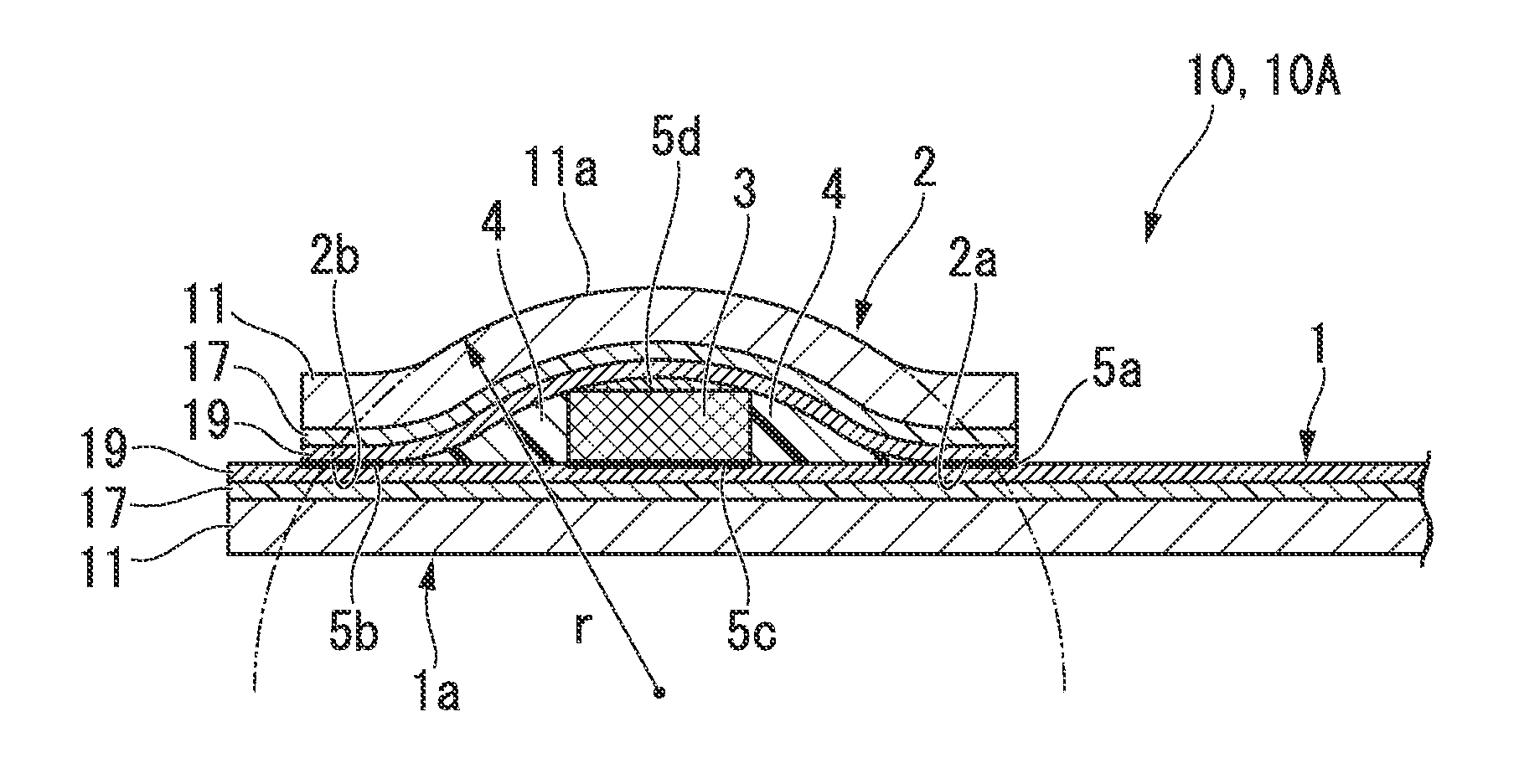
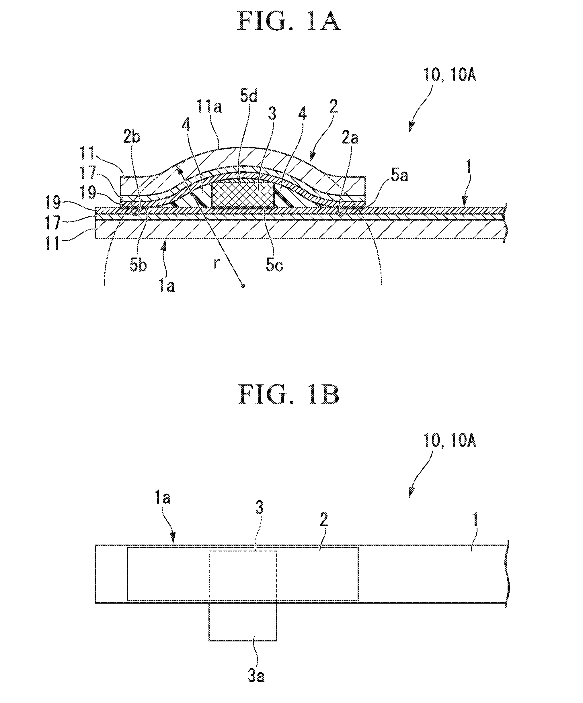
[0088]A plurality of superconducting wires having the electrode unit joining structure having a structure shown in FIGS. 1A and 1B were prepared similarly to Example 1 except that a radius of curvature r of a base member of the superconducting wire cover rod was changed to 6 to 19 mm.

[0089]With respect to the plurality of the superconducting wires that were obtained, a critical current (IC) at a nitrogen temperature (77 K) was measured, and a degree of variation (IC / IC0) with respect to a critical current (IC0) of the superconducting wire before the joining of the superconducting cover tape was calculated. FIG. 4 shows a relationship between (IC / IC0) and the radius of curvature r (mm) of the surface of the base member of the superconducting wire cover rod.

[0090]As shown in FIG. 4, when the radius of curvature r of the surface of the base member of the superconducting wire cover rod was 11 mm or less, the critical current was lowered. On the contrary to this, when the radius of curva...


PUM


Abstract

An electrode unit joining structure for a superconducting wire includes: a superconducting wire comprising a first base member, a first superconducting layer provided on the first base member, and a first electroconductive layer provided on the first superconducting layer; an electrode provided on the first electroconductive layer at an end portion of the superconducting wire; and a superconducting cover tape comprising a second base member, a second superconducting layer provided on the second base member, and a second electroconductive layer provided on the second superconducting layer, the superconducting cover tape being provided so as to cover at least part of the electrode, wherein the second electroconductive layer of the superconducting cover tape is disposed on the electrode side, and the electrode, the superconducting wire, and the superconducting cover tape are electrically connected to each other.

Description

CROSS REFERENCE TO RELATED APPLICATIONS[0001]This application is a continuation application based on a PCT Patent Application No. PCT / JP2011 / 058774, filed Apr. 7, 2011, whose priority is claimed on Japanese Patent Application No. 2010-095377, filed Apr. 16, 2010, the entire content of which are hereby incorporated by reference.BACKGROUND OF THE INVENTION[0002]1. Field of the Invention[0003]The present invention relates to an electrode unit joining structure for a superconducting wire, a superconducting wire, and a superconducting coil.[0004]2. Description of the Related Art[0005]In recent years, various equipment devices as electric power application equipment using a superconducting wire that is obtained by processing a superconductor into the wire rod have been developed. For example, a superconducting magnetic energy storage (hereinafter, simply referred to as “SMES”) has characteristics such as an energy input and output speed that is faster than other energy storages, and thus ...

Claims


Application Information

Patent Timeline
Patent Type & Authority Patents(United States)
IPC IPC(8): H01L23/48
CPCH01L39/02H01L39/2435H01L39/2461H01F6/065H01L2924/0002H01L2924/00H10N60/80H01B12/02H01R4/68H01F6/00H01F6/06
Inventor HARAGUCHI, MASASHIFUJITA, SHINJIDAIBO, MASANORI
Owner FUJIKURA LTD
Why Eureka
Try Eureka