
Apparatus and method for processing piston

a technology of outer circumferential surface and apparatus, which is applied in the direction of grinding drive, grinding machine components, manufacturing tools, etc., can solve the problems of coarse surface roughness of the outer circumferential surface after the process, and inability to achieve high-accuracy three-dimensional process. achieve the effect of smooth surface roughness

Inactive Publication Date: 2013-08-06
KOGANEI SEIKI
View PDF31 Cites 4 Cited by
  • Summary
  • Abstract
  • Description
  • Claims
  • Application Information

AI Technical Summary

Benefits of technology

The present invention provides an apparatus and method for processing the outer circumferential surface of a piston material three-dimensionally with high-accuracy to manufacture a piston that improves fuel efficiency. The apparatus uses a detection system to obtain positional information of the outer surface of the piston material, which is then controlled to process the material into a three-dimensional shape with high-accuracy. The grinding process can be selectively performed on areas of the grinding surface of the grinding wheel, resulting in a smoother surface after the process. The grinding surface is segmented into rough-grinding and finishing areas, allowing for higher-accuracy processing and smoother surface roughness.

Problems solved by technology

However, by a turning process, since an outer circumferential surface of a piston material is ground by a turning tool, a high-accuracy three-dimensional process cannot be done.
In addition, surface roughness of the outer circumferential surface after the process is coarse.
In addition, by a cutting process, since an outer circumferential surface of a piston material is ground by a cutting tool, a high-accuracy three-dimensional process cannot be done.
In addition, surface roughness of the outer circumferential surface after the process is coarse.

Method used


Image

  • Apparatus and method for processing piston
  • Apparatus and method for processing piston
  • Apparatus and method for processing piston

Examples


Embodiment Construction

[0022]An embodiment of an apparatus for processing a piston according to an embodiment will be explained with reference to the drawings, hereinafter.

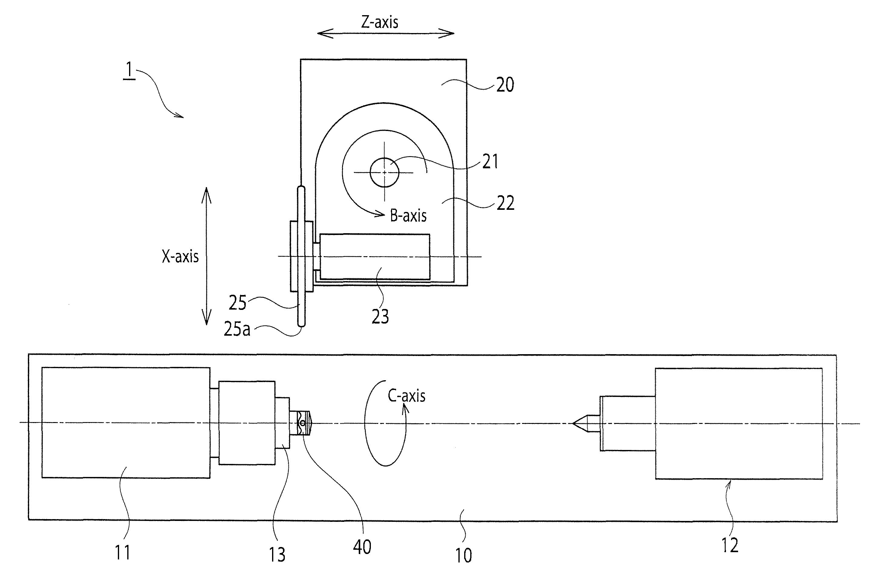
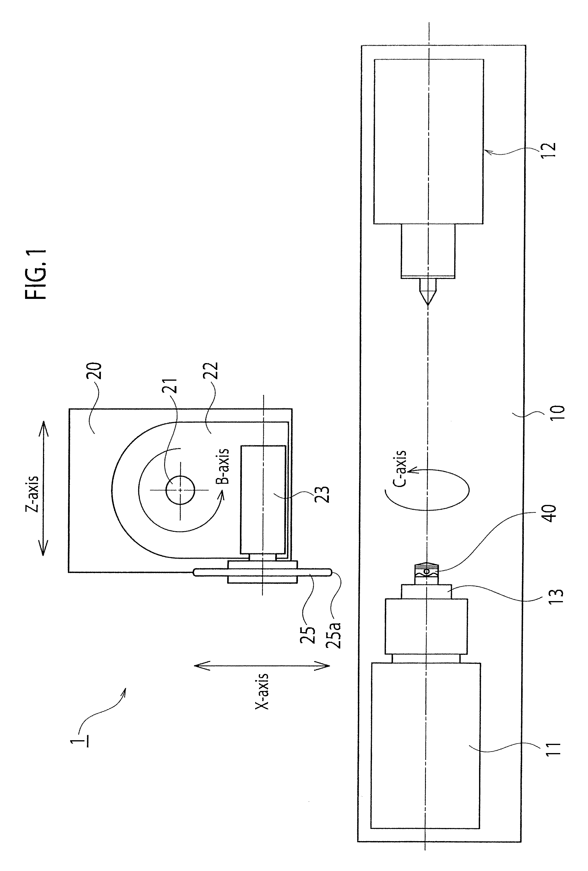
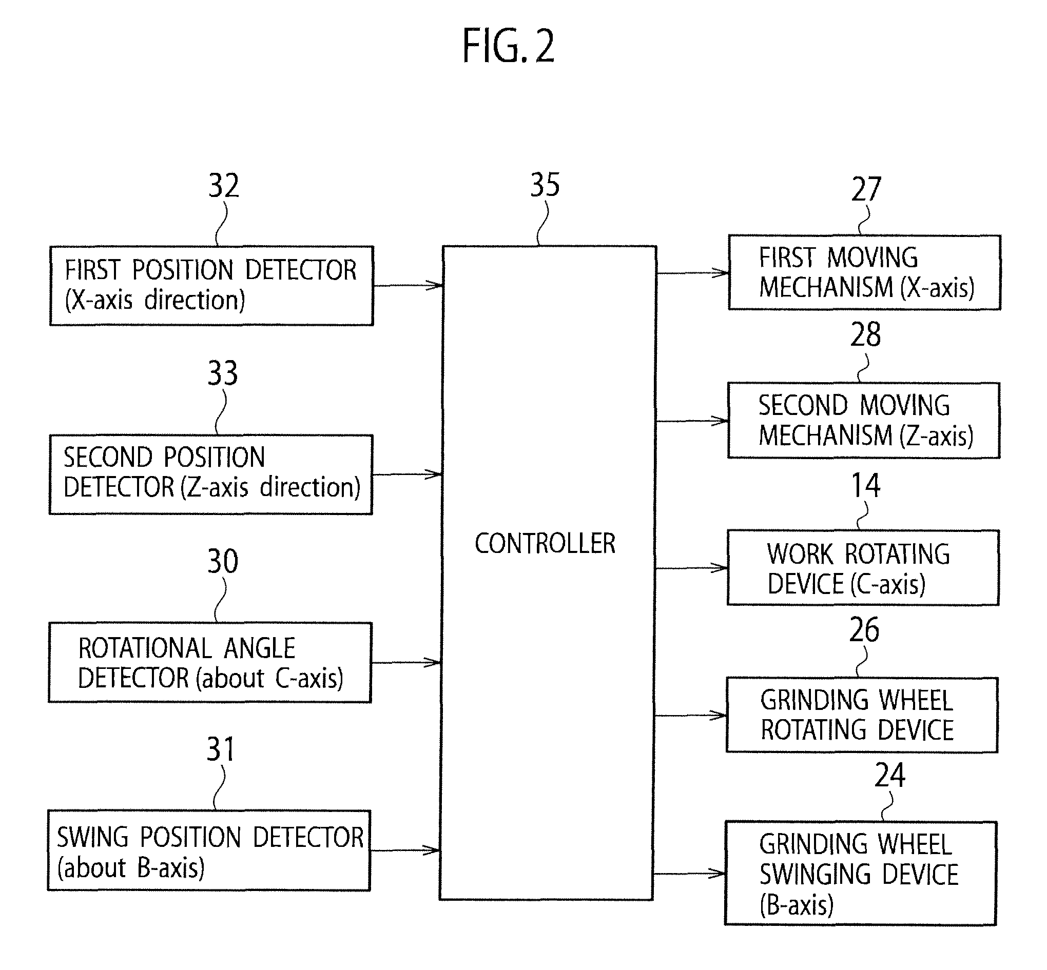
[0023]As shown in FIG. 1 and FIG. 2, the piston processing apparatus 1 includes a work bench 10 and a grinding wheel bench 20. A head support base 11 and a position measuring instrument 12 are disposed on the work bench 10. A work attaching head 13 is rotatably supported on the head support base 11. A piston material 40 that is a work to be processed can be attached onto the work attaching head 13. The piston material 40 is made of aluminum alloy, and fixed to the work attaching head 13 in a state where a center axis of its outer circumferential surface is made coincident with a rotational center of the work attaching head 13. The work attaching head 13 is rotated about a C-axis by a work rotating device 14. The piston material 40 is rotated due to a rotation of the work attaching head 13, so that a rotational angle of the piston materi...


PUM

PropertyMeasurementUnit
distanceaaaaaaaaaa
rotational angle detectoraaaaaaaaaa
rotational angleaaaaaaaaaa

Abstract

A piston processing apparatus includes a work attaching head capable of fixing a piston material, a work rotating device, a grinding wheel, a grinding wheel rotating device, first and second moving mechanisms for moving the grinding wheel, a rotational angle detector for detecting a rotational angle of the work attaching head, a first and second position detectors for detecting a position of a grinding surface of the grinding wheel, a controller controls the first and second moving mechanisms to grind the outer circumferential surface by the grinding wheel based on target-position information of the grinding surface corresponding to a position on the outer circumferential surface of the piston material. According to the piston processing apparatus, the outer circumferential surface of the piston material can be processed into a three-dimensional shape with high-accuracy, and a piston that can improve fuel efficiency.

Description

CROSS-REFERENCE TO RELATED APPLICATION[0001]This application is based upon Japanese Patent Application No. 2008-137805, filed on May 27, 2008 (published as Japanese Patent Application Laid-Open No. 2009-285742 on Dec. 10, 2009); the entire contents of which are incorporated herein by reference for all purposes.BACKGROUND[0002]1. Field[0003]The present invention relates to an apparatus and a method for processing an outer circumferential surface of a piston.[0004]2. Description of Related Art[0005]It is desired that a shape of an outer circumferential surface of a piston reciprocating in an internal combustion engine is formed so as to bring a constant gap to an inner surface of a cylinder at all positions in view of thermal expansion at combustion and so on. Therefore, it is needed to process a shape of an outer circumferential surface of a piston material three-dimensionally (to process it into a shape having a three-dimensional surface change to an ellipsoidal reference circumfere...

Claims


Application Information

Patent Timeline
Patent Type & Authority Patents(United States)
IPC IPC(8): B24B1/00
CPCB24B19/10B24B47/22
Inventor OSAKA, SHUJI
Owner KOGANEI SEIKI
Learn More