Method and apparatus for controlling the temperature of molds, dies, and injection barrels using fluid media

a technology of fluid media and temperature control, applied in the direction of domestic cooling apparatus, lighting and heating apparatus, instruments, etc., can solve the problems of limiting the precision and reliability of the temperature control process, and achieve the effect of increasing the cooling potential

Active Publication Date: 2013-08-06
MOLDCOOL INT
View PDF38 Cites 8 Cited by
  • Summary
  • Abstract
  • Description
  • Claims
  • Application Information

AI Technical Summary

Benefits of technology

[0014]The prior art provides several techniques for restoring the return line temperature or post process temperature to a supply line temperature or temperature that will provide a surplus of heating or cooling capacity to the control loop and hence to the molding machine. However, the effectiveness of these techniques varies considerably based on system design, component selection, and overall operating conditions, all of which limits the precision and reliability of the temperature control process. In one respect, the invention relates to the control the temperature and volume of fluid in the temperature control system, in real time or near real time, shifting the basis of control to the precision delivery of thermal energy to the molding machine in a manner that compensates for the lack of precision in a mainly temperature control system.
[0017]It is therefore a goal of the invention to provide a more energy efficient circulator by eliminating the slippage losses encountered in a centrifugal pump. It is well known within centrifugal pump manufacturing companies that centrifugal pumps add heat to the pumped media in the form of viscous heat dissipation caused by churning the liquid when the fluid is spun centrifugally out of the pump. Moreover the pump delivery in a centrifugal pump is not linear and is always spoken of as a curve where the highest volumetric delivery is called the “nominal rating” of the centrifugal pump. In a positive displacement pump there is no slippage as with a centrifugal pump because these pumps use positive displacement gears, rotors or pistons to move the flow. A positive displacement pumps' volumetric delivery curve is flat or linear. The slippage in a centrifugal pump requires a larger pump and motor to be used to get the same volumetric throughput. For example, in one closed loop circulator something on the order of a seven horsepower motor is required to achieve a delivery pressure of 50 psi. A circulator in accordance with the invention can use a smaller, more efficient servo motor and positive displacement pump to achieve the same 50 psi pressure with the same resultant volumetric throughput. In molds where the cooling channels are seen to be small and restricted the flow rate will be substantially reduced. The large seven horsepower motor and pump will be generating little actual flow and there will be substantial heating of the cooling fluid by the centrifugal pump itself.
[0018]Further, the additional heat imparted to the cooling media by a centrifugal pump has to be removed by a central chilling system, adding a further waste, cost or inefficiency to conventional systems. It is a goal of the invention to reduce or eliminate this source of inefficiency and to consume less power to achieve the required flow rate.
[0019]In one aspect, a circulator of the invention can be set up to operate at low energy consumption, metering coolant using the central chiller pumping system for energy force. The servo motor and fixed displacement pump perform merely to regulate the flow. This type of pump does not chum the coolant and thereby generate heat which must be removed. Because a circulator in accordance with the invention is not imparting excess work-heat to the fluid, the central chilling system can be smaller and more energy efficient.
[0020]A circulator according to some aspects of the invention allows for programming behavior that is not possible with a conventional, constant speed motor / centrifugal pump arrangement. When an electronic, servo motor driven, positive-displacement pump is controlling the fluid flow based on rotational position, desirable profiles of flow or flow rate versus time can be generated and dynamically adjusted or controlled in real time based on sensor data to control the mold, die or injection barrel thermal condition. In conventional circulators, supply and return line pressure variations and voltage supply line variations are not compensated for and these fluctuations can cause change in volumetric throughput. The result is that even if the coolant loop temperature is held precisely constant at the sensor location, the rate of cooling flow or BTU's / second delivered in the mold may be much different. According to one embodiment of the invention, the circulator by means of its electronic, servo motor driven, positive-displacement pump is able to precisely meter this energy rate of coolant to the mold, die or injection barrel, thereby providing an improved method of temperature control for molding processes.
[0026]With the ability to tailor a flow delivery profile, the curve can be adjusted, for example, to be delivered with a high or low peak at any point in the molding cycle. Using a sensor in the mold wall, die wall or injection barrel wall, a time / temperature curve can be generated that will reflect the mold cavity temperature each cycle of the molding machine. This time / temperature curve is then converted into a heat energy / time delivery curve or thermal profile tailored to the cooling or heating requirements of the process. The delivery of the thermal profile can be advanced in time ahead of the peak measured temperature or general measured temperature profile to account for the time lag or hysteresis effects required to accomplish the higher thermal transfer between the machine mass and the fluid for optimal control in the mold, die or barrel.

Problems solved by technology

However, the effectiveness of these techniques varies considerably based on system design, component selection, and overall operating conditions, all of which limits the precision and reliability of the temperature control process.

Method used


Image

  • Method and apparatus for controlling the temperature of molds, dies, and injection barrels using fluid media
  • Method and apparatus for controlling the temperature of molds, dies, and injection barrels using fluid media
  • Method and apparatus for controlling the temperature of molds, dies, and injection barrels using fluid media

Examples


Embodiment Construction

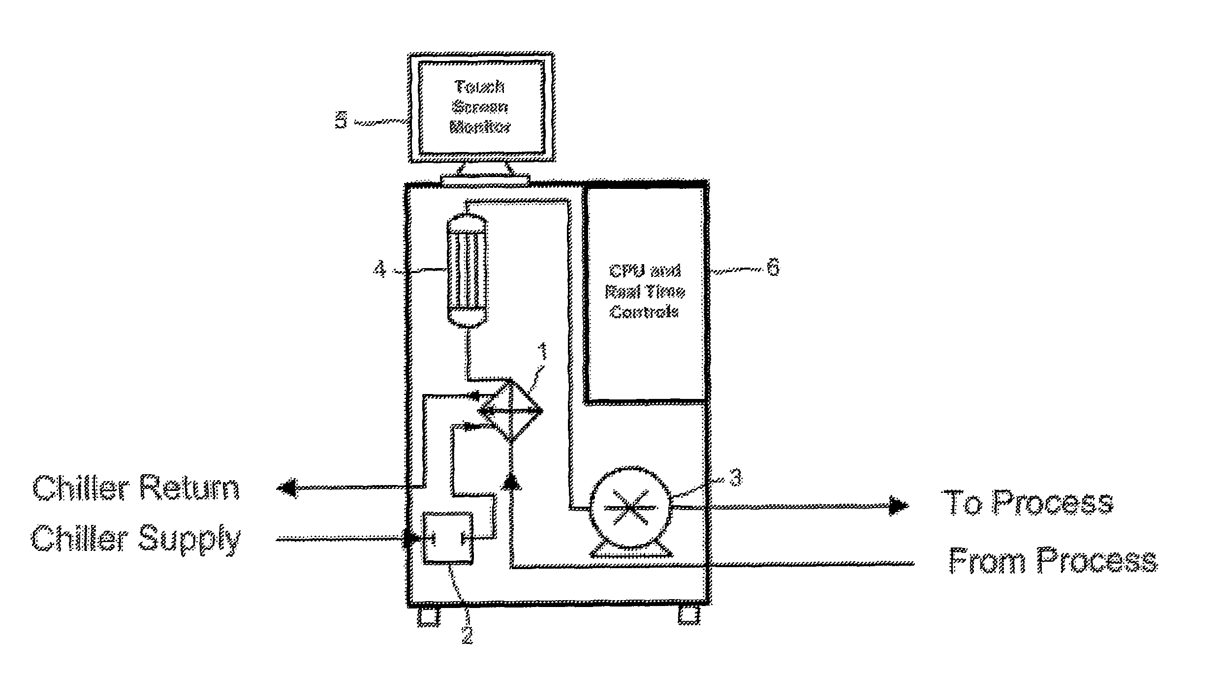
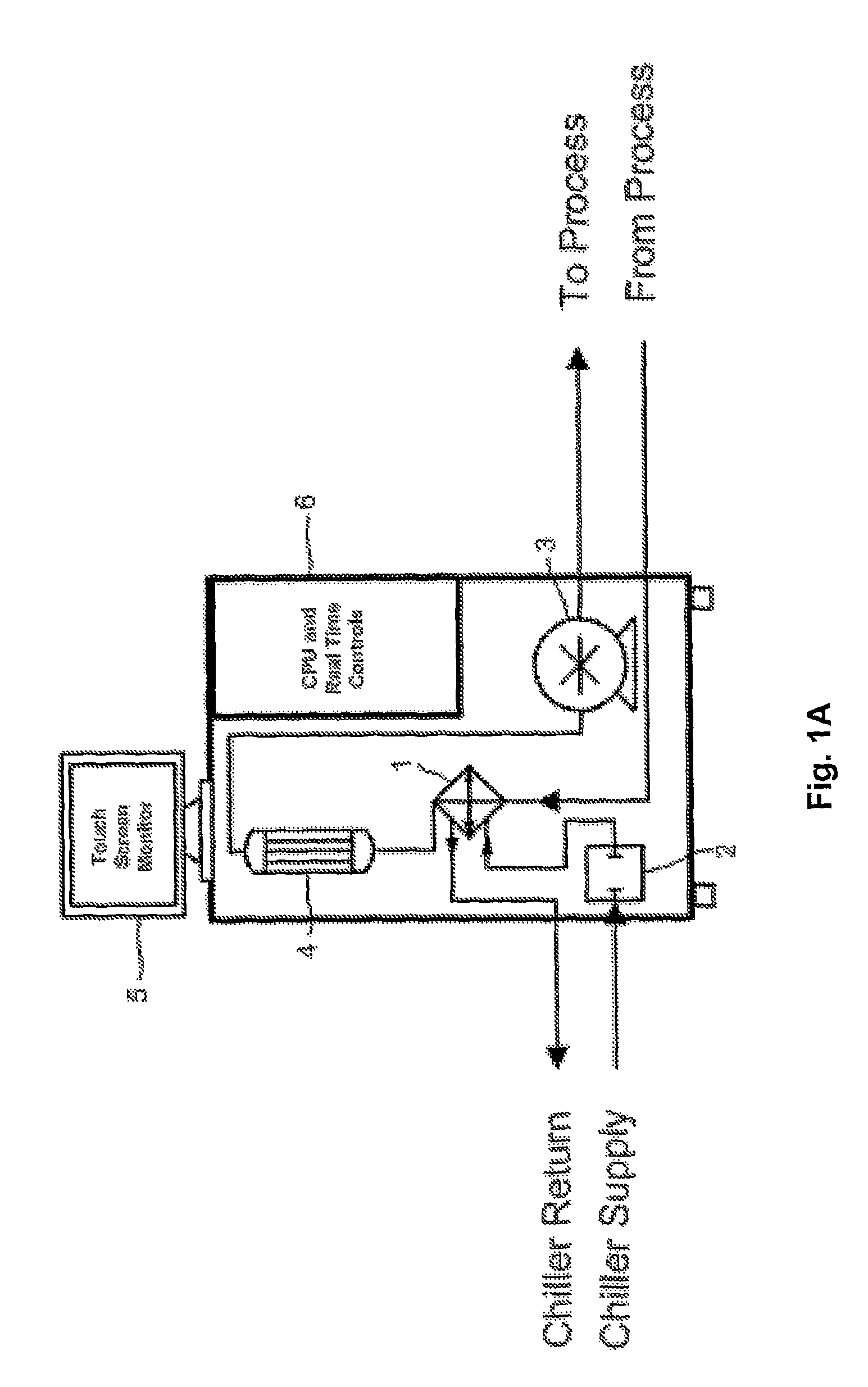
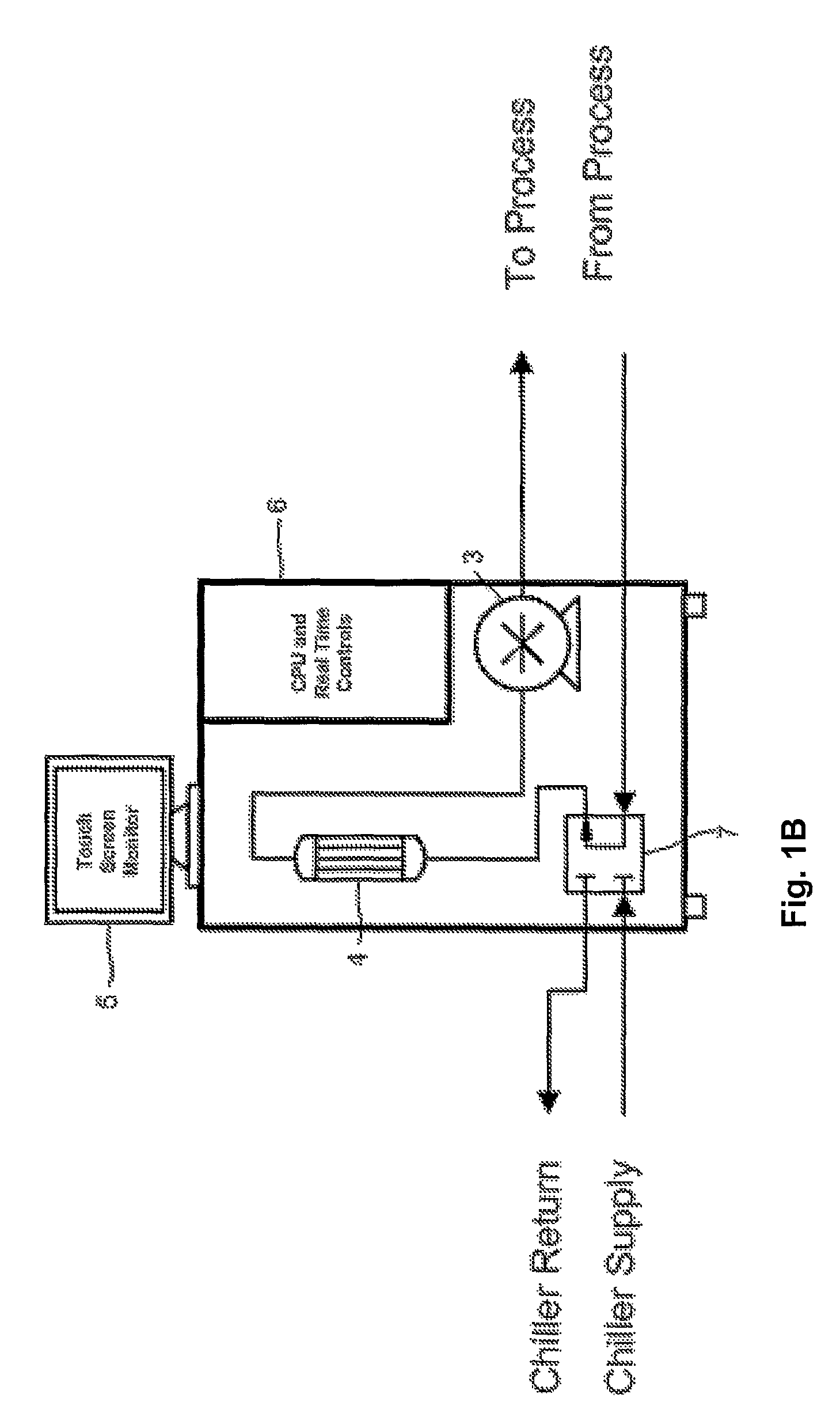
[0043]One embodiment of the present invention provides an electronic servo motor operating a positive displacement thermal control fluid pump as part of an injection molding temperature control system, commonly called a “circulator” or circulator system. An electronic servo motor is somewhat tolerant of supply line voltage fluctuations that will vary the speed of a conventional motor. The positive displacement pump meters exact quantities of thermal control fluid or coolant in proportion to controlled revolutions of the stepping motor. This circulator system is used to control the temperature of a mold, die or injection barrel by circulating a fluid medium, at a suitably lower or higher temperature depending on whether the process is exothermic or endothermic, through a network of channels in the mold in the conventional manner, adding or extracting heat from the mold. The loop of pre-heated or pre-cooled fluid that is plumbed from the circulator pump to the mold, die or injection b...


PUM

PropertyMeasurementUnit
temperatureaaaaaaaaaa
pressureaaaaaaaaaa

Abstract

For controlling temperature in the molding of plastics, metal, ceramic, or die-casting, a circulator supporting a molding machine includes a fixed displacement pump driven by an electronic servo motor for volumetric metering of thermal fluid to or from the molding machine. A pre-set or dynamically controlled volume and flow rate profile matches the heating and cooling requirement of a molding machine and process. Volumetric metering may be based on parameters such as time, machine cycle status, temperature, pressure, and / or flow rate. Fluid may be circulated through the mold at positive or negative pressure at fixed, variable, or pulsed flow. The supply side in a fluid loop may be restricted so as to cause a pressure drop in or upstream of the mold, die or barrel, and seed bubbles may be injected into the fluid flow to excite vaporization and lowering of the fluid temperature.

Description

[0001]This application is a National Phase Application filed under 35 USC §371 of PCT Application No. PCT / US2007 / 062023, filed 13 Feb. 2007, which is a continuation of U.S. application Ser. No. 11 / 352,894, filed 13 Feb. 2006. Each of these applications are herein incorporated by reference in their entirety for all purposes.FIELD OF THE INVENTION[0002]The invention relates to thermal control systems and methods for exerting thermal control with a thermal fluid circuit, and more particularly, to thermal control systems and methods for use with a mold, die or injection barrel.BACKGROUND OF THE INVENTION[0003]A thermal fluid circulator in the context of the invention is a device or system that is commonly used in the plastics, metals, ceramics, and die cast molding industries in the control of operating temperatures of molds, dies or injection barrels. Circulator systems may incorporate a built-in chiller. Central chilling systems need a main circulator pumping system. Alternatively, th...

Claims


Application Information

Patent Timeline
Patent Type & Authority Patents(United States)
IPC IPC(8): B29C47/92B29C48/92
CPCG05D23/1919B29C45/7306B29C47/92B29C35/007B29C2945/76545B29C2945/76782
Inventor JOHNSON, KENNETH E.
Owner MOLDCOOL INT
Why Eureka
Try Eureka