Light emitting diode driving apparatus and method for holding driving voltage thereof

a technology of led driving apparatus and light-emitting diodes, which is applied in the direction of electric variable regulation, process and machine control, instruments, etc., can solve the problems of severe electro-magnetic interference and damage to components, and achieve the effect of mitigating the generated over current phenomenon

Inactive Publication Date: 2013-08-06
NOVATEK MICROELECTRONICS CORP
View PDF1 Cites 2 Cited by
  • Summary
  • Abstract
  • Description
  • Claims
  • Application Information

AI Technical Summary

Benefits of technology

[0008]The invention is directed to a light emitting diode (LED) driving apparatus, which can mitigate an over current phenomenon generated in the LED driving apparatus when a dimming status is changed.
[0009]The invention is directed to a method for holding a driving voltage of a LED, which can mitigate an over current phenomenon generated in a driving apparatus when a dimming status is changed.
[0012]According to the above descriptions, in a dimming on state, the feedback voltage generated according to the driving voltage of the LED is sampled and held to generate the pre-storage voltage. In a dimming off state, the pre-storage voltage and the feedback voltage are compared to determine whether or not to generate the pre-charge clock signal to stable a voltage value of the driving voltage. In this way, the voltage value of the driving voltage does not have excessive voltage drop due to excessively long time of the dimming off state, and when the dimming on state is re-entered, excessively large current generated by an inductor in the LED driving apparatus is avoided, so as to avoid a severe electro-magnetic interference (EMI).

Problems solved by technology

Such derived large inducting current IL may cause a severe electro-magnetic interference (EMI), and may also cause damage of components in the LED driving apparatus 100.

Method used


Image

  • Light emitting diode driving apparatus and method for holding driving voltage thereof
  • Light emitting diode driving apparatus and method for holding driving voltage thereof
  • Light emitting diode driving apparatus and method for holding driving voltage thereof

Examples


Embodiment Construction

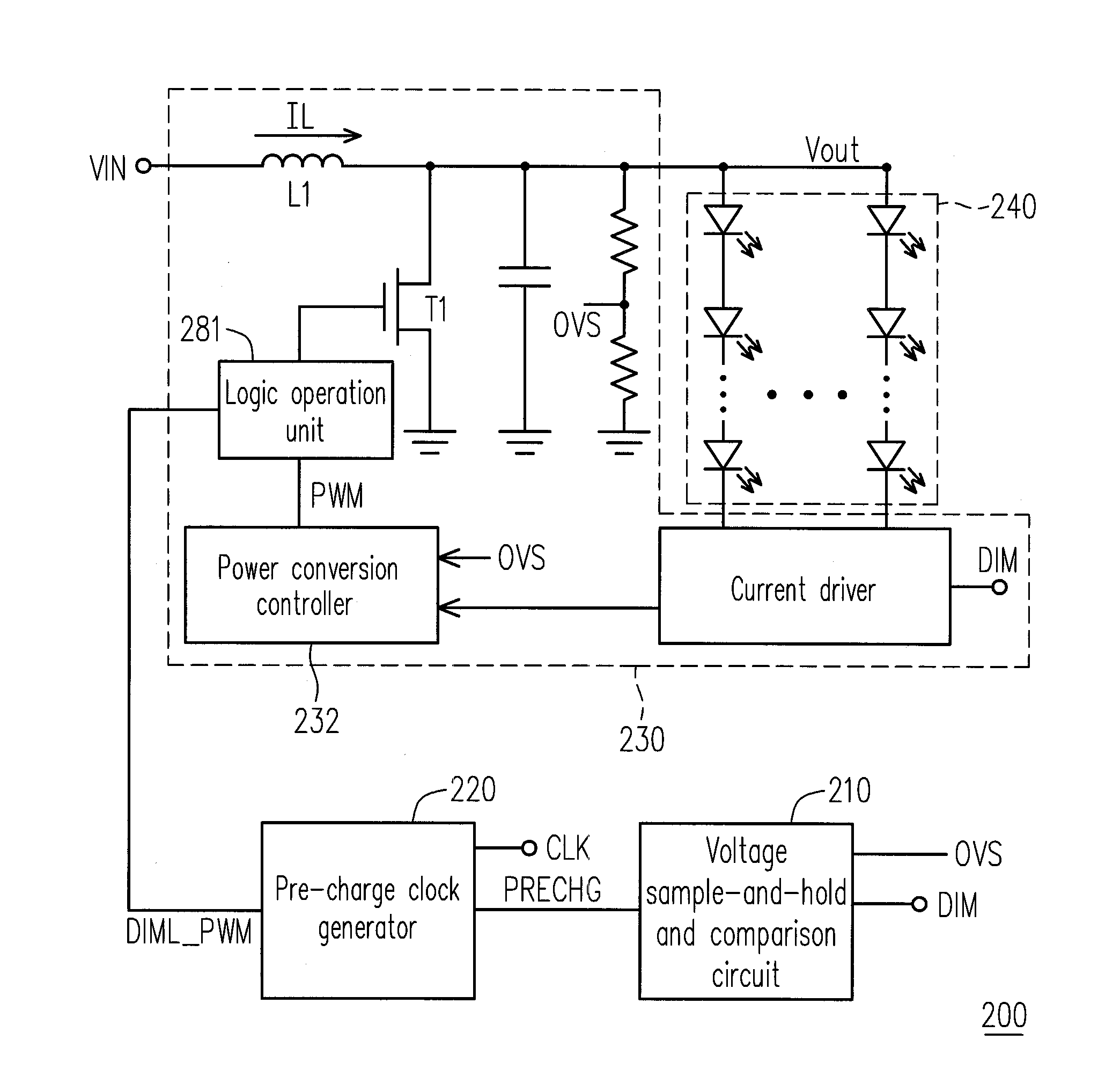
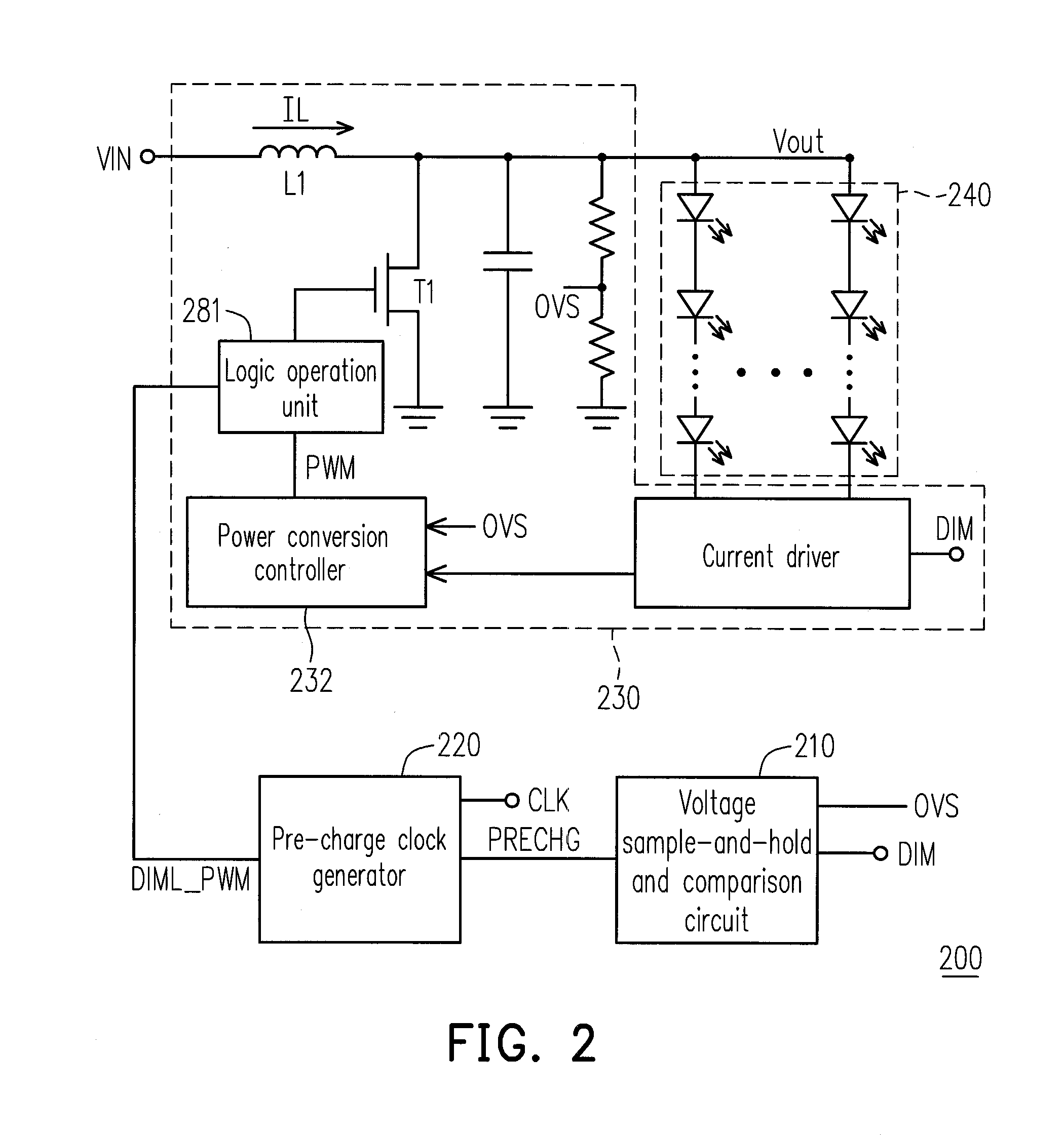
[0021]Referring to FIG. 2, FIG. 2 is a schematic diagram of a light emitting diode (LED) driving apparatus 200 according to an embodiment of the invention. The LED driving apparatus 200 includes a voltage sample-and-hold and comparison circuit 210, a pre-charge clock generator 220 and a power converter 230. The power converter 230 includes a power transistor switch T1. The power converter 230 receives an input voltage VIN and performs power conversion by turning on or off the power transistor switch T1, so as to output a driving voltage Vout at an output terminal of the LED driving apparatus 200 for driving a LED string 240.

[0022]The voltage sample-and-hold and comparison circuit 210 is coupled to the output terminal of the LED driving apparatus 200 for receiving a feedback voltage OVS generated according to the driving voltage Vout. In the present embodiment, the feedback voltage OVS is generated by dividing a voltage level of the driving voltage Vout. The voltage sample-and-hold a...


PUM


Abstract

A light emitting diode (LED) driving apparatus is disclosed. The LED driving apparatus includes a power converter, a voltage sample-and-hold and comparison circuit, and a pre-charge clock generator. The power converter has a power transistor switch for processing power conversion and outputs a driving voltage at an output terminal. The voltage sample-and-hold and comparison circuit enters a sample-and-hold mode or a comparing mode according to a dimming status signal. The voltage sample-and-hold and comparison circuit samples and holds a feedback voltage to obtain a pre-storage voltage during the sample-and-hold mode and compares the pre-storage voltage with the feedback voltage to obtain a comparison result during the comparing mode. The voltage sample-and-hold and comparison circuit generates a pre-charge enable signal according to the comparison result. The pre-charge clock generator generates a pre-charge clock signal to control the power transistor switch according to the pre-charge enable signal and a clock signal.

Description

CROSS-REFERENCE TO RELATED APPLICATION[0001]This application claims the priority benefit of Taiwan application serial no. 99142169, filed on Dec. 3, 2010. The entirety of the above-mentioned patent application is hereby incorporated by reference herein and made a part of this specification.BACKGROUND[0002]1. Field of the Invention[0003]The invention relates to a light emitting diode (LED) driving apparatus. Particularly, the invention relates to a method for holding a driving voltage of a LED driving apparatus.[0004]2. Description of Related Art[0005]FIG. 1 is a schematic diagram of a conventional light emitting diode (LED) driving apparatus 100. In the LED driving apparatus 100, in order to drive a LED string 130 to produce a normal brightness, a power converter 120 of the LED driving apparatus 100 receives and transmits a cross voltage of the conducted LED string 130 through a current driver 122 to serve as a reference voltage VFB, and the LED driving apparatus 100 adjusts a magni...

Claims


Application Information

Patent Timeline
Patent Type & Authority Patents(United States)
IPC IPC(8): H05B37/02
CPCH05B33/0824H05B33/0815H05B33/0827Y02B20/346H05B45/3725H05B45/38H05B45/44H05B45/46Y02B20/30
Inventor CHANG, TSUNG-HAUCHIU, CHIA-LIN
Owner NOVATEK MICROELECTRONICS CORP
Why Eureka
Try Eureka