Torsion beam manufacturing method and torsion beam

a manufacturing method and technology of torsion beam, applied in the direction of transportation and packaging, metal-working apparatus, interconnection systems, etc., can solve the problems of deteriorating the endurance of torsion beam disadvantageous in view of productivity and cost in the same manner, etc., to achieve the effect of enhancing the fatigue strength of the ear portion, reducing the residual tensile stress in the inner surface, and reducing the tensile stress in the ear portion

Active Publication Date: 2013-08-13
JFE STEEL CORP
View PDF15 Cites 6 Cited by
  • Summary
  • Abstract
  • Description
  • Claims
  • Application Information

AI Technical Summary

Benefits of technology

[0007]We provide a means which can overcome the above-mentioned drawbacks, and can enhance fatigue strength of an ear portion which is a high risk part of the fatigue crack initiation in a torsion beam almost without bringing about disadvantages in terms of productivity and cost.
[0021]A residual tensile stress of the ear portion of the torsion beam can be reduced, and also work hardening can be applied to the ear portion so that a fatigue strength of the ear portion can be enhanced. With respect to steps, a step in which slight bending of 2 to 6% is applied is only added after the usual crushing step. That is, the restriction on a length of a manufactured tube is equal to the corresponding restriction in a usual manufacturing method, and it is unnecessary to add steps such as grinding, applying torsion and heat treatment. Hence, disadvantages of the manufacturing method in terms of productivity and cost are extremely small to be ignored.

Problems solved by technology

These wrinkles become a source of fatigue crank initiation and deteriorate the endurance of the torsion beam.
Hence, there arises a drawback that the technique is disadvantageous in view of productivity and cost.
Hence, the technique also has a drawback that it is disadvantageous in view of productivity and cost in the same manner.

Method used


Image

  • Torsion beam manufacturing method and torsion beam
  • Torsion beam manufacturing method and torsion beam
  • Torsion beam manufacturing method and torsion beam

Examples


example 1

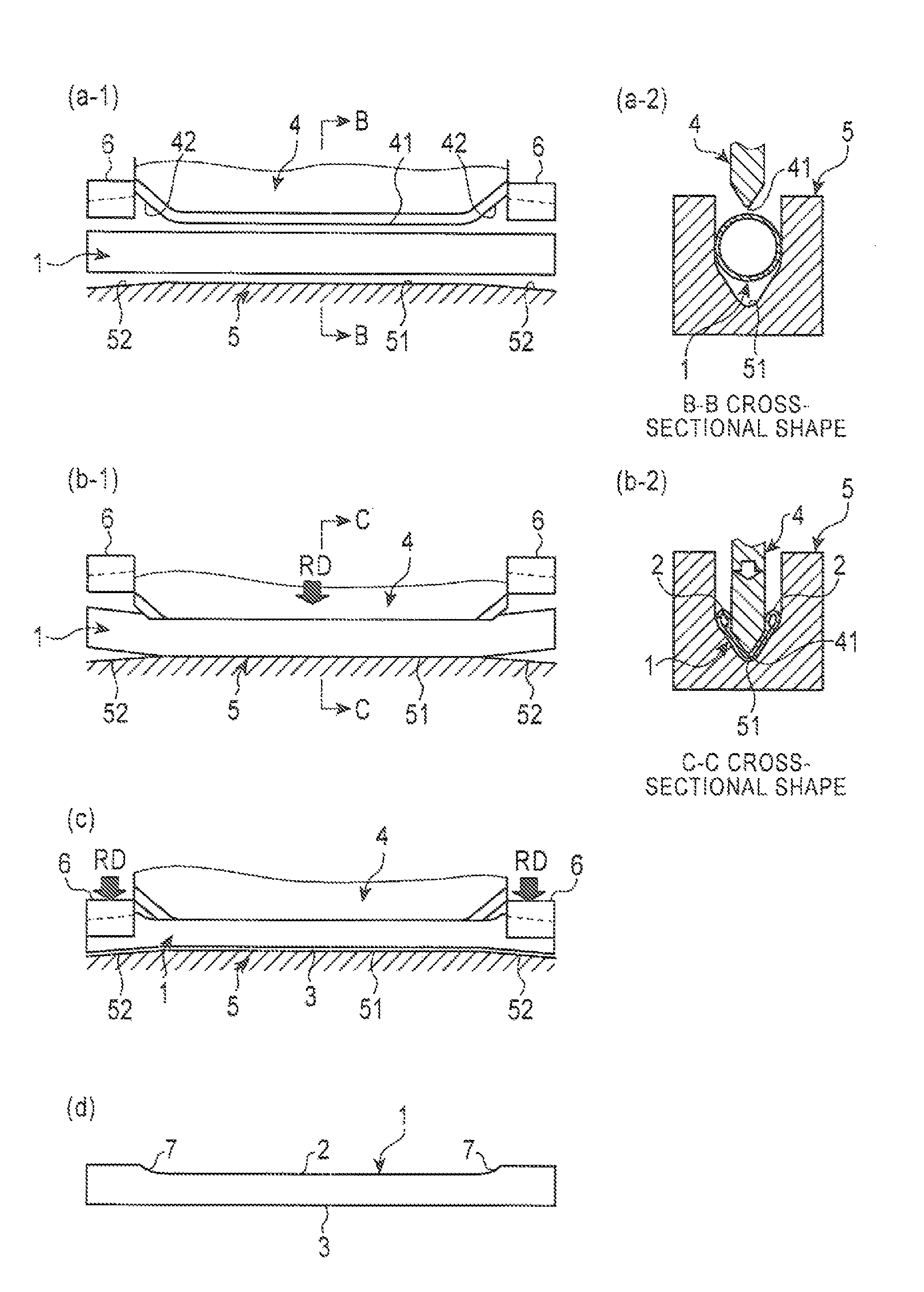
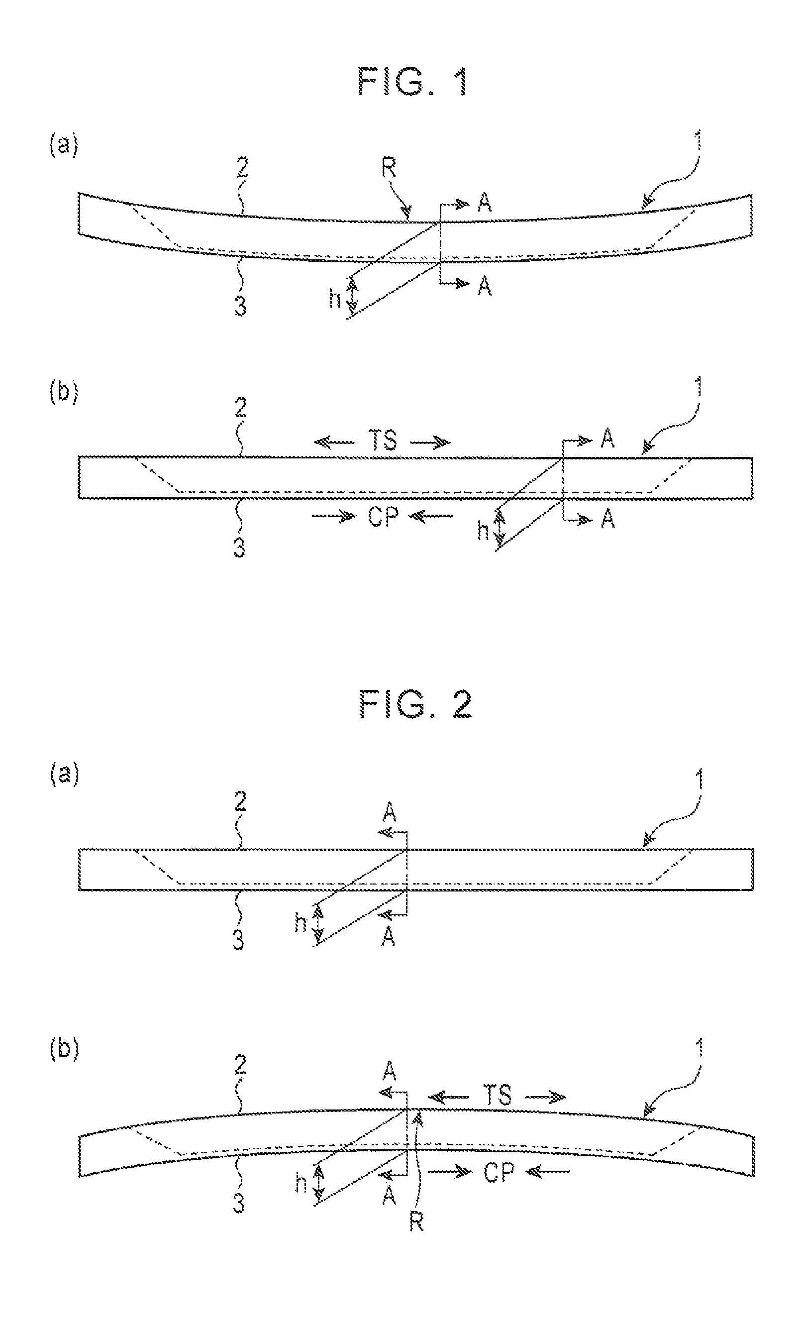
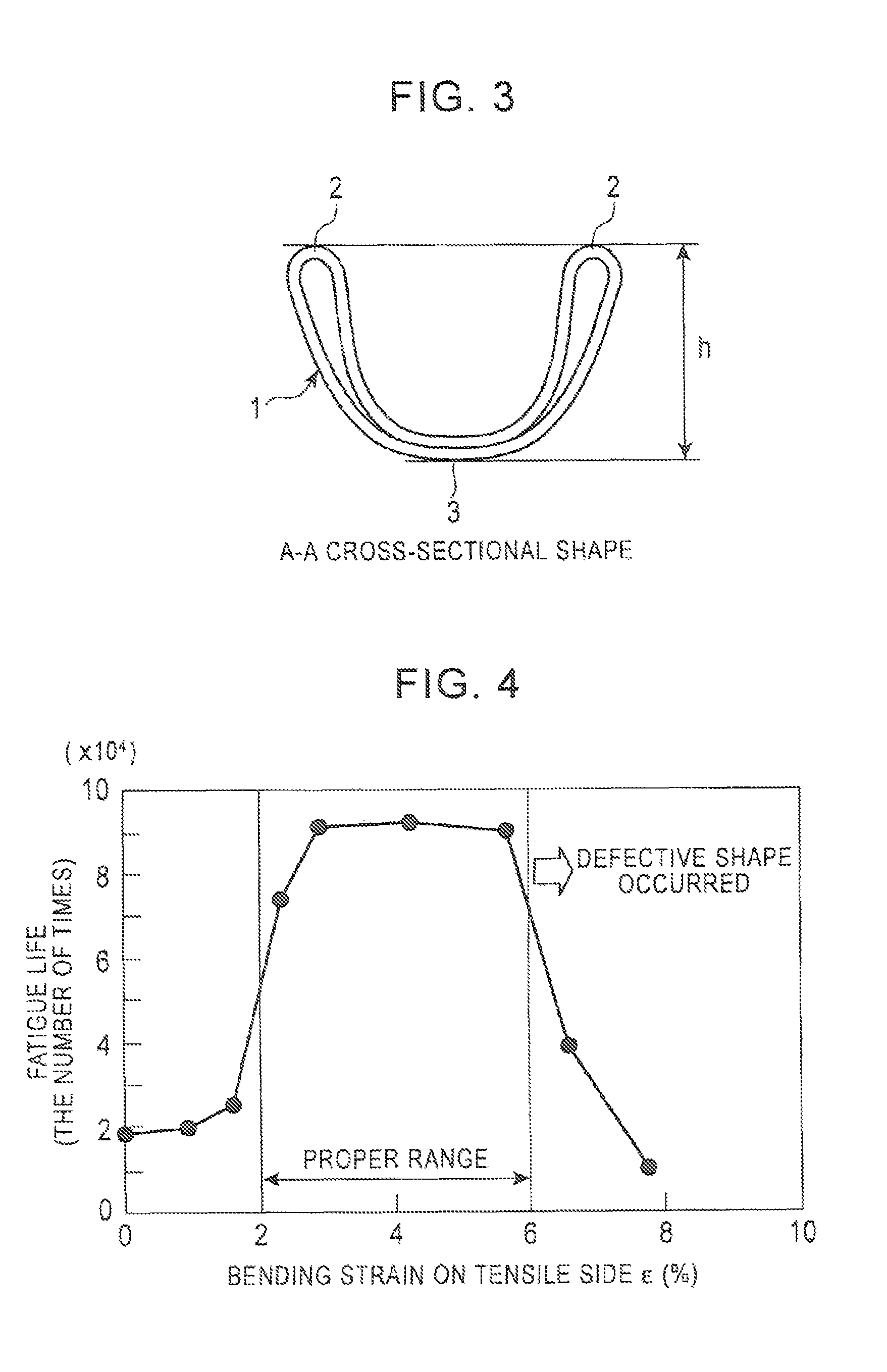
[0081]As Example 1, torsion beams were manufactured by forming tubular bodies made of raw tubes (tubes in raw configuration being circular tubes) shown in Table 1 under different forming conditions shown in Table 2 in the example shown in FIG. 1 or FIG. 2, and endurance lifetimes (the number of times) of these torsion beams were investigated by carrying out a fatigue test substantially equal to the above-mentioned fatigue test on the manufactured torsion beams. The result of the test is shown in Table 2. From Table 2, it is understood that our Examples exhibit extremely long endurance lifetimes compared to Comparison Examples, and no defective shape is found in our Examples.

example 2

[0082]As Example 2, torsion beams were manufactured by forming tubular bodies of raw tubes (tubes in raw configuration being circular tubes) shown in Table 1 under different forming conditions shown in Table 3 in the example of any one of the above-mentioned methods (2) to (9), and endurance lifetimes (the number of times) were investigated by carrying out a fatigue test substantially equal to the above-mentioned fatigue test on the manufactured torsion beams. The result of the test is shown in Table 3-1 to Table 3-4.

[0083]From Table 3-1 to Table 3-4, it is understood that our Examples exhibit extremely long endurance lifetimes compared to the Comparison Examples, and no defective shape is found in our Examples. Further, the result of the above-mentioned γ obtained using the above-mentioned measuring method is also shown in Table 3-1 to Table 3-4. In our Examples, γ is suppressed to 50% or less.

[0084]

TABLE 1raw tensile strengthouter diameter wall thickness length tube(Mpa)(mm)(mm)(m...


PUM

PropertyMeasurementUnit
lengthaaaaaaaaaa
thicknessaaaaaaaaaa
outer diameteraaaaaaaaaa

Abstract

A method enhances fatigue strength of ear portions which are high fatigue risk parts in a torsion beam almost without bringing about disadvantages in terms of productivity and cost. A torsion beam is formed with a portion of the tubular body into an approximately U-shape in cross section by crushing the portion of the tubular body in the radial direction and, thereafter, due to bending with a bottom line set as a belly side of bending, a bending strain of 2 to 6% in the tube longitudinal direction on a tensile side is imparted to the ear portions.

Description

RELATED APPLICATIONS[0001]This is a §371 of International Application No. PCT / JP2010 / 056286, with an international filing date of Mar. 31, 2010 (WO 2010 / 114173 A1, published Oct. 7, 2010), which is based on Japanese Patent Application Nos. 2009-088907, filed Apr. 1, 2009, and 2010-061753, filed Mar. 18, 2010, the subject matter of which is incorporated by reference.TECHNICAL FIELD[0002]This disclosure relates to a torsion beam manufacturing method and a torsion beam, and more specifically to a torsion beam manufacturing method where a tubular body which is a circular tube in a raw configuration is formed into a torsion beam having an approximately U-shape or V-shape in cross section by forming, and a torsion beam which is manufactured by the torsion beam manufacturing method.BACKGROUND[0003]To consider a case where a torsion beam is manufactured in such a manner that a tubular body is manufactured by a normal tube manufacturing method (a tube manufacturing method where the rolling d...

Claims


Application Information

Patent Timeline
Patent Type & Authority Patents(United States)
IPC IPC(8): B21D31/00
CPCB21D9/15B21D11/02B21D17/02B21D22/025B60G21/051B21D53/88Y10T29/49622B60G2206/30B60G2206/80B60G9/04
Inventor HASHIMOTO, YUJITOYODA, SHUNSUKENAKAGAWA, KINYASUZUKI, KOJIKAWABATA, YOSHIKAZUSONOBE, OSAMUSATO, AKIO
Owner JFE STEEL CORP
Why Eureka
Try Eureka