
X-ray dark-field imaging system and method

a dark-field imaging and x-ray technology, applied in the field of xray imaging, can solve the problems of insufficient observation insufficient manufacture of required optical elements, and insufficient recognition of hard x-ray dark-field imaging technology

Active Publication Date: 2013-08-20
TSINGHUA UNIV +1
View PDF10 Cites 18 Cited by
  • Summary
  • Abstract
  • Description
  • Claims
  • Application Information

AI Technical Summary

Benefits of technology

The present invention is about a way to get information about how scattered rays of light are distorting an image. This information can be measured by looking at the decrease in brightness of the image. The invention has come up with a way to turn this information into a quantitative measure, which can be used to reconstruct the image using a traditional algorithm. This technique helps to improve the accuracy of the image and make it easier to analyze and interpret.

Problems solved by technology

As for dark-field imaging, due to the particular optical properties of hard x-rays, the manufacture of required optical elements is very difficult, and accordingly, the hard x-rays dark-field imaging can hardly be better fulfilled all along.
In the 90s of the twentieth century, as the third-generation synchronous radiation source develops and the manufacturing level of delicate hard x-ray optical elements rises, the study of hard x-ray dark-field imaging technology gains certain growth, but as compared with the hard x-ray phase contrast imaging technology rising simultaneously, the hard x-ray dark-field imaging technology has always been insufficiently noticed due to low semaphore, comparatively difficult detection, long time of imaging, etc.
However, since the synchronous radiation device has a large volume, costs much and enables a small field of view, it confines the hard x-ray dark-field imaging technology to great extent in terms of applications in medical clinics and industrial detection.

Method used


Image

  • X-ray dark-field imaging system and method
  • X-ray dark-field imaging system and method
  • X-ray dark-field imaging system and method

Examples


Embodiment Construction

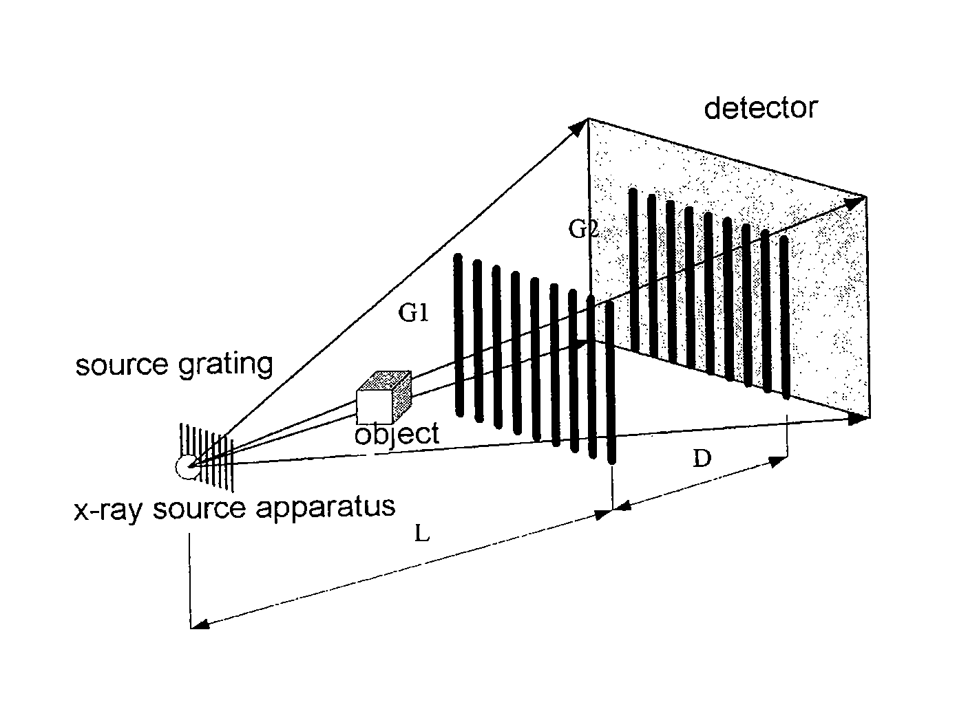
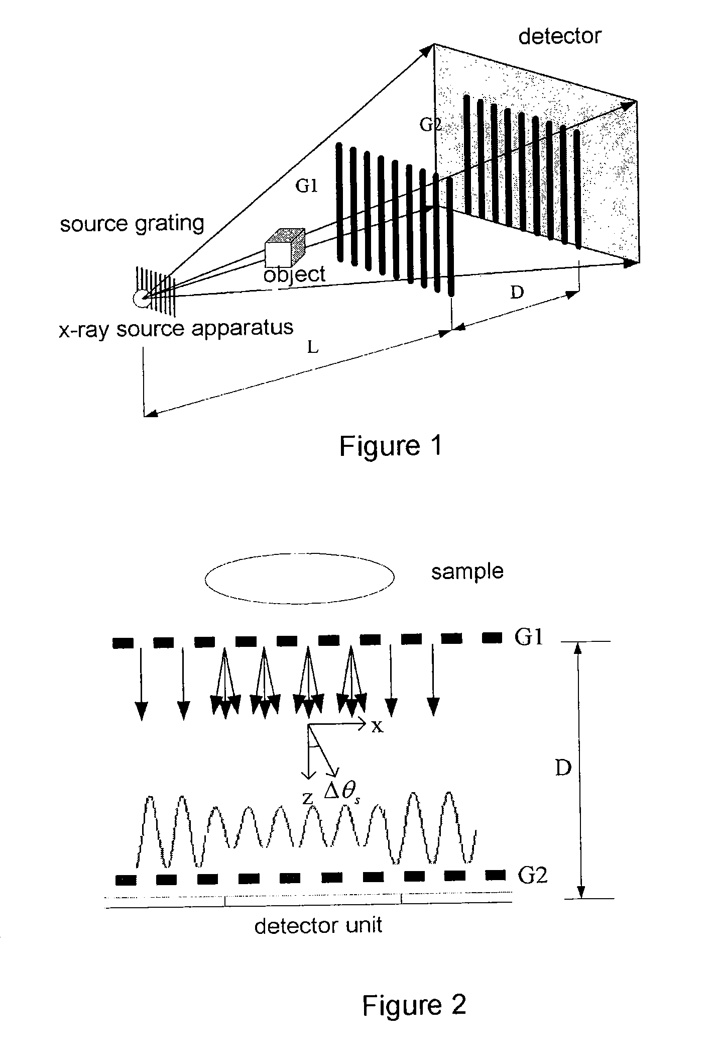
[0032]By reference to FIG. 1, according to the principle of the present invention, an x-ray grating dark-field imaging system comprises: an x-ray apparatus S, an optional source grating G0, two absorbing gratings (i.e. first and second absorbing gratings G1 and G2), and a detector, which are orderly positioned in a propagation direction of the x-rays. The x-ray apparatus may be an all-purpose x-ray generator.

[0033]Preferably, the cycle of the two absorbing gratings is between 0.1 and 30 μm. The gratings use heavy metal as the absorbing material, and to take gold (Au) for example, the height of the gold is determined by the x-ray energy applied, which is between 10 and 100 μm. For example, for x-rays of 20 keV, gold with a height of more than 16 μm can block 90% of the x-rays.

[0034]Preferably, the detector can be a matrix detector, wherein each detection unit (pixel) can detect the intensity variation of the incident x-rays.

[0035]Specifically, the x-ray apparatus is used for emitting...


PUM


Abstract

An x-ray imaging technology, performing an x-ray dark-field CT imaging of an examined object using an imaging system which comprises an x-ray source, two absorbing gratings G1 and G2, an x-ray detector, a controller and a data processing unit, comprising the steps of: emitting x-rays to the examined object; enabling one of the two absorbing gratings G1 and G2 to perform phase stepping motion within at least one period range thereof; where in each phase stepping step, the detector receives the x-ray and converts it into an electric signal; wherein through the phase stepping of at least one period, the x-ray intensity at each pixel point on the detector is represented as an intensity curve; calculating a second moment of scattering angle distribution for each pixel, based on a contrast of the intensity curve at each pixel point on the detector and an intensity curve without presence of the examined object; taking images of the object at various angles, then obtaining an image with scattering information of the object in accordance with a CT reconstruction algorithm.

Description

[0001]The present application is the national phase application of PCT Application No. PCT / CN2010 / 001010, filed Jul. 6, 2010, which claims priority to Chinese Patent Application No. 200910088662.8, filed Jul. 7, 2009, the entireties of both of which are hereby incorporated by references.TECHNICAL FIELD[0002]The present invention relates to x-ray imaging field, and specifically to a technology of performing dark-field imaging of an object using x-rays.BACKGROUND[0003]In prior art devices such as CT, scanning imaging of an object using x-rays has been widely used. However, the traditional x-ray imaging examines the internal structure of an object without destruction by using attenuation property of a material for x-rays, and this belongs to x-ray bright-field imaging technology.[0004]In optical imaging field, dark-field imaging is remarkably different from bright-filed imaging. Dark-field imaging is a technology of imaging a substance using non-direct light (e.g. scattered light, diff...

Claims


Application Information

Patent Timeline
Patent Type & Authority Patents(United States)
IPC IPC(8): A61B6/00G03B42/02
CPCB82Y10/00G01N23/04G01N23/20075G21K2207/005G21K2201/061G01N23/041
Inventor HUANG, ZHIFENGCHEN, ZHIQIANGZHANG, LIWANG, ZHENTIANXING, YUXIANGZHAO, ZIRANXIAO, YONGSHUN
Owner TSINGHUA UNIV
Learn More