Driving force controller for vehicle

a technology for driving force controllers and vehicles, applied in the direction of electrical control, instruments, computing, etc., can solve the problems of inability to continuously delay the ignition timing, and restricted control of delaying the ignition timing, so as to reduce the driving force of vehicles, avoid the effect of increasing the temperature of exhaust gas of engines and the resultant deterioration of exhaust gas purification catalysts

Active Publication Date: 2013-08-20
TOYOTA JIDOSHA KK
View PDF20 Cites 2 Cited by
  • Summary
  • Abstract
  • Description
  • Claims
  • Application Information

AI Technical Summary

Benefits of technology

[0008]A main object of the present invention is to effectively reduce driving force of a vehicle, in a state where the driving force of the vehicle must be reduced, while avoiding an increase in the temperature of exhaust gas of an engine and resultant deterioration of an exhaust gas purification catalyst, the object being achieved by effectively utilizing delaying of the ignition timing or reduction of the fuel supply amount to a possible extent, while preventing elongation of the execution time of control of delaying the ignition timing or control of reducing the fuel supply amount.
[0009]The present invention provides a driving force controller for a vehicle comprising throttle-opening control means for controlling a throttle opening of an engine on the basis of at least an amount of drive operation by a driver; engine-output reduction means for reducing an output of the engine through delaying of ignition timing of the engine or reduction of an amount of fuel supplied to the engine; and driving-force reduction control means for determining the degree of necessity of reducing a driving force of the vehicle on the basis of travel conditions of the vehicle and for reducing the output of the engine by controlling at least the throttle-opening control means when the degree of necessity is high, the driving force controller being characterized in that, when the degree of necessity is equal to or higher than a first reference value, the driving-force reduction control means reduces the throttle opening controlled by the throttle-opening control means, and, when the degree of necessity is equal to or higher than a second reference value greater than the first reference value, the driving-force reduction control means reduces the output of the engine by the engine-output reduction means as well as reducing the throttle opening controlled by the throttle-opening control means.

Problems solved by technology

However, when the ignition timing is delayed, the temperature of exhaust gas of the engine increases, which causes deterioration of an exhaust gas purification catalyst.
Therefore, the ignition timing cannot be delayed continuously, and a period over which the control for delaying the ignition timing is performed is restricted to a short period of time.
However, the control of completely closing the throttle valve cannot reduce the output of the engine with good responsiveness, and, thus, cannot reduce the driving force of the vehicle with good responsiveness.
H7-84850 does not take into consideration the execution time of the ignition-timing delay control, and may cause an increase in the temperature of exhaust gas of the engine and resultant deterioration of the exhaust gas purification catalyst.
H7-84850 has a problem of being unable to clear strict emission control standards enacted in recent years.
However, since execution of the ignition-timing delay control is restricted to a predetermined period of time which starts from a point in time when reduction of the engine output through control of reducing the throttle opening is started, the execution time of the ignition-timing delay control must be restricted to a very short time in order to prevent an increase in the temperature of exhaust gas of the engine in all travel conditions of the vehicle.
Accordingly, the driving force controller has a problem that the effect of reducing the vehicle driving force through the ignition-timing delay control is limited.
Such a problem arises, for example, in the case where drive slippages of the drive wheels occur immediately after the vehicle has started to move, the throttle-opening reduction control and the ignition-timing delay control are started in order to cope with the drive slippages, and the ignition-timing delay control is ended after elapse of a predetermined time.
In such a case, even when drive slippages of the drive wheels continuously occur after that point in time, the ignition-timing delay control cannot be executed, and the drive slippages cannot be effectively reduced by means of reducing the engine output through the ignition-timing delay control.
However, when the amount of fuel supplied to the engine is reduced, as in the case of the ignition-timing delay control, the temperature of exhaust gas of the engine increases, which causes deterioration of the exhaust gas purification catalyst.

Method used


Image

  • Driving force controller for vehicle
  • Driving force controller for vehicle
  • Driving force controller for vehicle

Examples


first embodiment

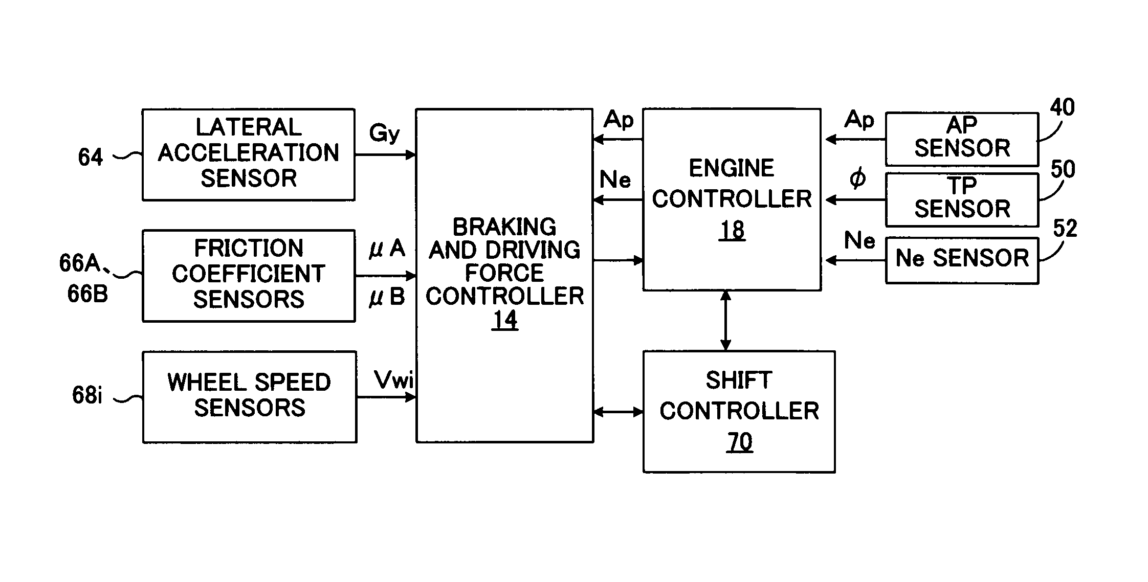
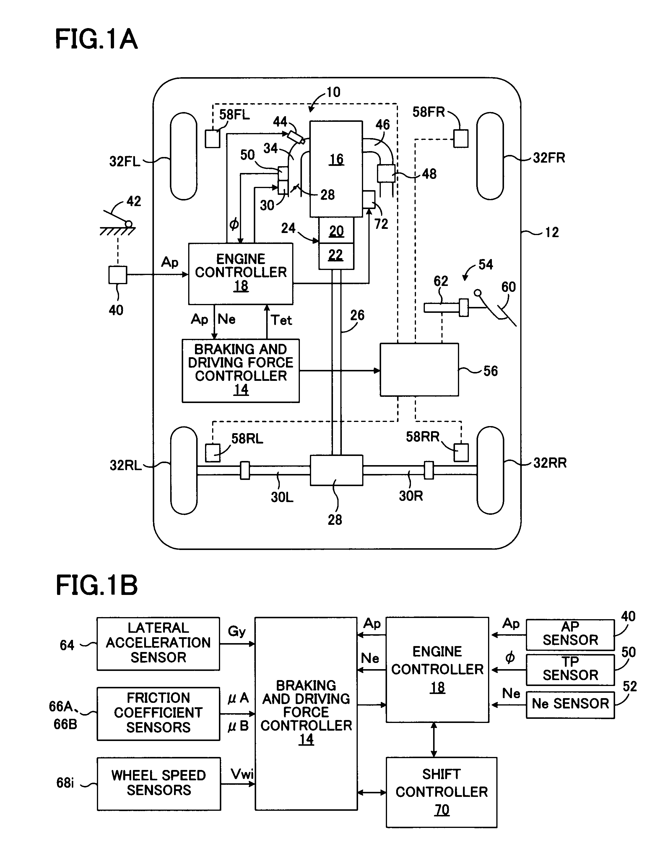
[0080]FIG. 1A is a schematic diagram showing a first embodiment of a vehicular driving force controller according to the present invention applied to a rear-wheel drive vehicle, and FIG. 1B is a block diagram of a control system thereof.

[0081]In FIG. 1, a driving force controller 10, which is mounted on a vehicle 12, includes a braking and driving force controller 14 that controls traveling motion of a vehicle by controlling braking and driving forces of the vehicle and the wheels; and an engine controller 18 that controls a spark ignition engine 16. The driving force of the engine 16 is transmitted to a propeller shaft 26 via an automatic transmission 24 which includes a torque converter 20 and a transmission 22. The driving force of the propeller shaft 26 is transmitted to left-rear and right-rear wheel axles 30L and 30R by a differential 28, whereby left and right rear wheels 32RL and 32RR, which are drive wheels, are rotated and driven.

[0082]Meanwhile, left and right front wheel...

second embodiment

[0129]FIG. 9 is a flowchart showing the vehicular target driving force and ignition timing correction control routine, which is achieved by the braking and driving force controller 14 in a second embodiment of the vehicular driving force controller according to the present invention. In FIG. 9, the same steps as those shown in FIG. 3 are denoted by the same step numbers as in FIG. 3.

[0130]In the present embodiment, the individual steps of the vehicular target driving force computation routine and the throttle opening and ignition timing control routine are executed in the same manner as in the above-described first embodiment. Although, steps 310 to 320, steps 335 to 345, and steps 355 to 390 are also executed in the same manner as in the above-described first embodiment, a step corresponding to step 350 in the first embodiment is omitted.

[0131]As shown in FIG. 9, when a positive determination is made in step 315, then in step 330, the target driving force Fxt1 to be achieved throug...

third embodiment

[0134]FIG. 11 is a flowchart showing the vehicular target driving force and ignition timing correction control routine, which is achieved by the braking and driving force controller 14 in a third embodiment of the vehicular driving force controller according to the present invention. In FIG. 11, the same steps as those shown in FIG. 3 are denoted by the same step numbers as in FIG. 3.

[0135]Also in the present embodiment, the individual steps of the vehicular target driving force computation routine and the throttle opening and ignition timing control routine are executed in the same manner as in the above-described first embodiment. Steps 310 to 345, and steps 380 to 390 of the vehicular target driving force and ignition timing correction control routine of the present embodiment are also executed in the same manner as in the above-described first embodiment. However, steps 360 and 365 are executed instead of steps 350 and 355 in the above-described first embodiment, respectively.

[0...


PUM


Abstract

An object of the present invention is to effectively reduce driving force of a vehicle, when the driving force of the vehicle must be reduced, while avoiding an increase in the temperature of exhaust gas and resultant deterioration of an exhaust gas purification catalyst, the object being achieved by effectively utilizing delaying of the ignition timing or reduction of the fuel supply amount to a possible extent, while preventing elongation of the execution time of control of delaying the ignition timing or control of reducing the fuel supply amount. When the driving force of the vehicle is excessively large, a target driving force Fxt is computed. When an indicator value SAa indicating the degree of necessity of reducing the driving force is equal to or greater than a first reference value SAa1, the throttle opening is reduced so that the driving force of the vehicle decreases more slowly than the target driving force Fxt. When the indicator value SAa is equal to or greater than a second reference value SAa2 greater than the first reference value SAa1, in addition to the reduction of the throttle opening, the ignition timing is delayed so that the driving force of the vehicle decreases faster than does in the case where only the reduction of the throttle opening is performed.

Description

TECHNICAL FIELD[0001]The present invention relates to a driving force controller for a vehicle, and more particularly, to a driving force controller which controls driving force of the vehicle through control of throttle opening of an engine and control of ignition timing.BACKGROUND ART[0002]For example, Japanese Patent Publication (kokoku) No. H7-84850 discloses a known driving force controller for a vehicle, such as an automobile, in which a spark ignition engine is mounted, the driving force controller controlling driving force of the vehicle through control of throttle opening of the engine and control of ignition timing. When drive slippages of drive wheels increase, the driving force controller lowers the output of the engine through control of fully closing the throttle valve and control of delaying the ignition timing, to thereby reduce the driving force of the vehicle. When the drive slippages of drive wheels decrease, the driving force controller first stops the control of...

Claims


Application Information

Patent Timeline
Patent Type & Authority Patents(United States)
IPC IPC(8): G06F17/00
CPCB60T8/175B60T8/1755B60W10/06B60W10/10B60W10/184B60W30/02B60W30/18172B60W30/188F02D29/02F02D37/02F02D41/12B60W2520/26B60W2710/06F02D11/105F02D41/0005F02D41/021F02D41/0235
Inventor OTAKE, HIROTADA
Owner TOYOTA JIDOSHA KK
Why Eureka
Try Eureka