Automatic soldering machine

a soldering machine and soldering terminal technology, applied in the direction of soldering apparatus, conductors,auxillary welding devices, etc., can solve the problems of high manufacturing cost, false soldering defects, and affecting the quality of soldering the cable with the terminal, so as to achieve stable quality and high manufacture efficiency

Inactive Publication Date: 2013-08-27
CHENG UEI PRECISION IND CO LTD
View PDF16 Cites 48 Cited by
  • Summary
  • Abstract
  • Description
  • Claims
  • Application Information

AI Technical Summary

Benefits of technology

[0006]As described above, the automatic soldering machine controls the loading tool by means of the man-machine control interface to make the automatic soldering machine proceed a series of manufacturing operations, such as the spraying hot molten solder operation, on the electronic products and the cables for realizing the automatic soldering process of the electronic products and the cables so as to replace a single point soldering way which is widely used in skilled field. As a result, the automatic soldering machine has a higher manufacture efficiency and the finished goods have a stable quality so as to meet a mass manufacture requirement.

Problems solved by technology

However, the aforesaid operation procedure of soldering the core wires of the cable with the terminals of the electronic product is executed by operators that often affects quality of soldering the cable with the terminals and even brings defects of false soldering, nonuniform soldered points and so on.
Furthermore, the operators need be trained for a long time that causes a higher manufacture cost, and it is so slow for the operators to manually execute the soldering process that it often fails to meet a mass manufacture requirement.

Method used


Image

  • Automatic soldering machine
  • Automatic soldering machine
  • Automatic soldering machine

Examples


Embodiment Construction

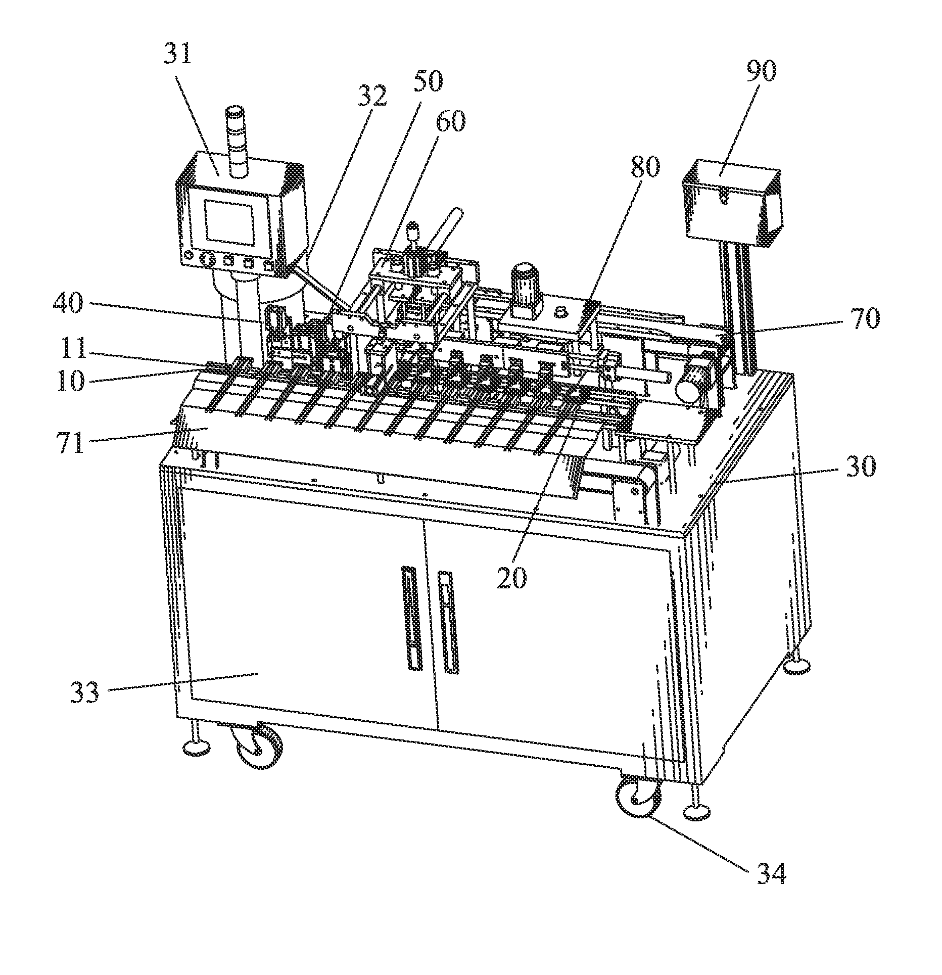
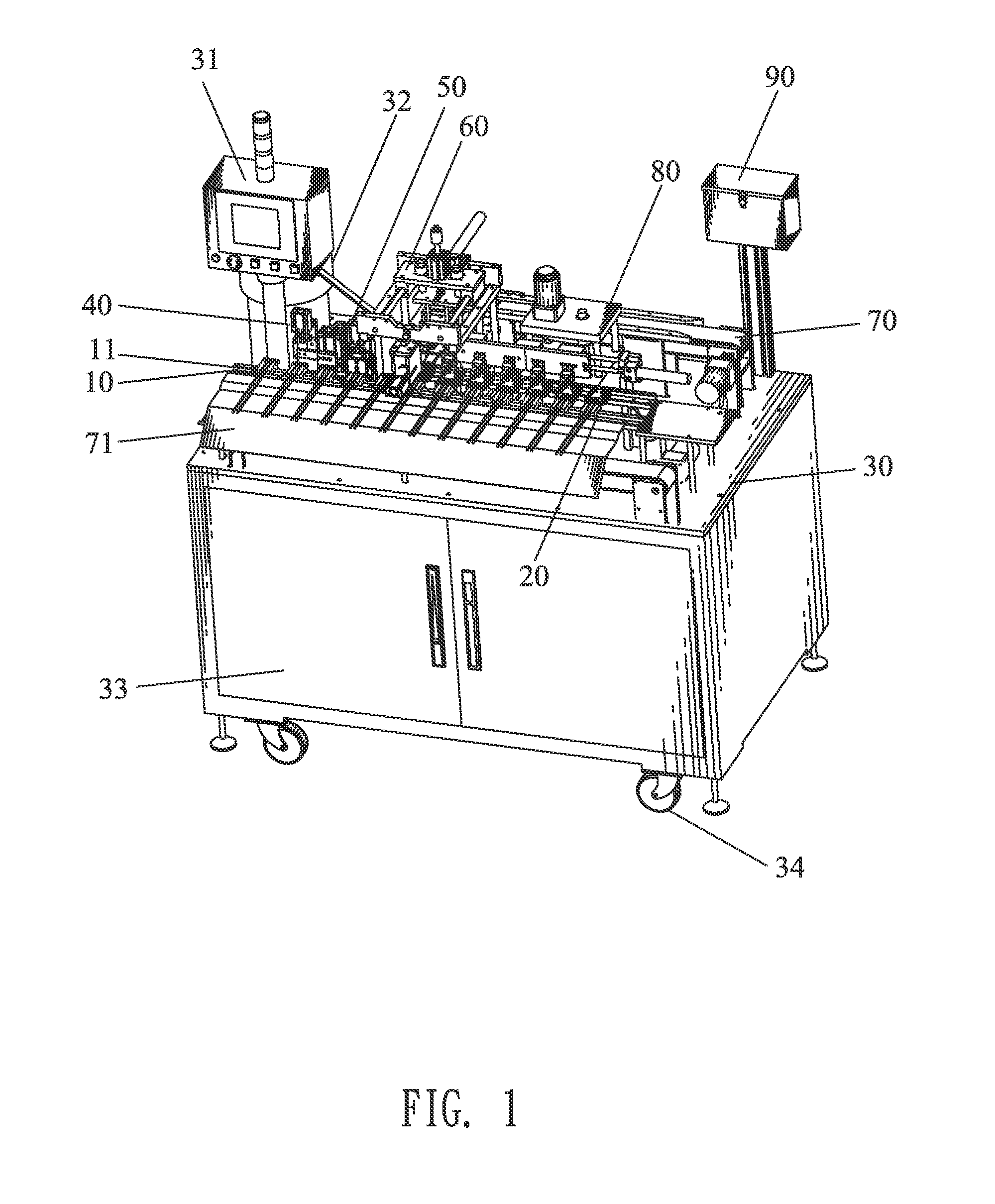
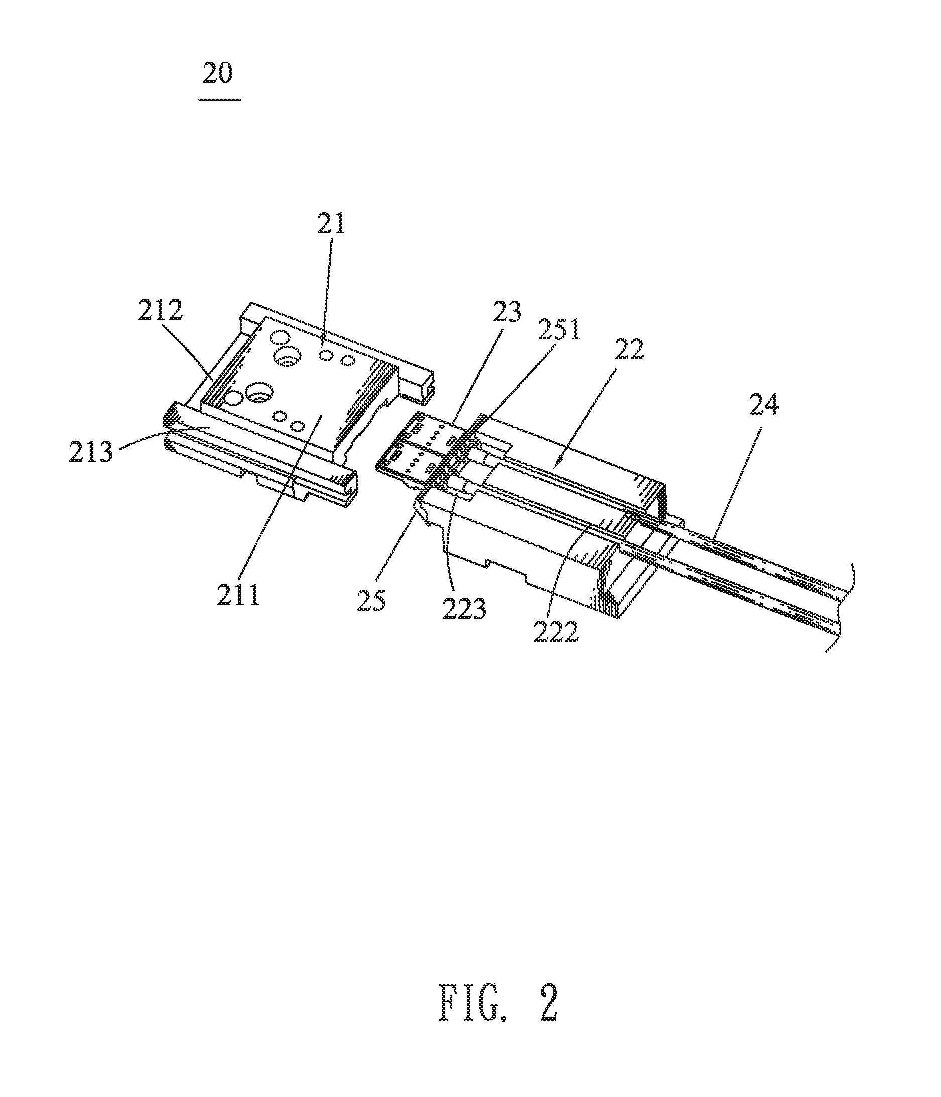
[0017]With reference to FIG. 1 and FIG. 2, an automatic soldering machine in accordance with the present invention is shown. The automatic soldering machine adapted for soldering cables 24 with electronic products 23 having soldering portions (not labeled) includes a loading tool 20, a main frame module 30, a man-machine control interface 31, a sliding tray 10, a feeding module 11, a removing module 40, a reforming module 50, a container 90, a loading tool combination module 60, a spraying module 80 and a loading tool reflow module 70.

[0018]The man-machine control interface 31 is mounted on one side of the main frame module 30. The sliding tray 10 is mounted on the main frame module 30, and is located in front of the man-machine control interface 31. The loading tool 20 is slidably disposed in the sliding tray 10 and includes a product loading body 21 for loading the electronic products 23 therein, and a cable loading body 22 for loading the cables 24 therein. The feeding module 11 ...


PUM

PropertyMeasurementUnit
angleaaaaaaaaaa
modulate relative anglesaaaaaaaaaa
stabilityaaaaaaaaaa

Abstract

An automatic soldering machine adapted for soldering cables with electronic products includes a main frame module, a man-machine control interface, a sliding tray located in front of the man-machine control interface, a loading tool slidably disposed in the sliding tray, a feeding module close to a bottom of the sliding tray, a removing module located between the man-machine control interface and a reforming module, a container, a loading tool combination module located above the sliding tray, a spraying module located in rear of the sliding tray, and a loading tool reflow module mounted on a rear of the main frame module. The man-machine control interface is connected with and controls the loading tool, the feeding module, the removing module, the reforming module, the loading tool combination module, the spraying module and the loading tool reflow module for realizing an automatic soldering process of the electronic products and the cables.

Description

BACKGROUND OF THE INVENTION[0001]1. Field of the Invention[0002]The present invention generally relates to an automatic soldering machine, and more particularly to an automatic soldering machine with a spraying solder function.[0003]2. The Related Art[0004]Generally, a cable is connected with an electronic product by means of soldering core wires of the cable with terminals of the electronic product. A usual operation procedure of soldering the core wires of the cable with the terminals of the electronic product is described as follows. At first, a portion of an insulator of the cable is stripped manually to expose the core wires. Then, a soldering gun is used for soldering the core wires of the cable with the terminals of the electronic product manually in a way of single point soldering. However, the aforesaid operation procedure of soldering the core wires of the cable with the terminals of the electronic product is executed by operators that often affects quality of soldering th...

Claims


Application Information

Patent Timeline
Patent Type & Authority Patents(United States)
IPC IPC(8): B23K37/00
CPCB23K37/00B23K1/0016B23K3/0638B23K2201/38B23K2101/38
Inventor YAN, AI-JUNWANG, WEIXIA, WEN-ZHI
Owner CHENG UEI PRECISION IND CO LTD
Why Eureka
Try Eureka