Chemical mechanical polishing machine and chemical mechanical polishing apparatus comprising the same

a mechanical polishing machine and mechanical polishing technology, which is applied in the direction of cutting machines, manufacturing tools, edge grinding machines, etc., can solve the problems of heavy weight of the cross-polishing head support of the conventional polishing machine, complex structure, and need for the planarization process of the deposition layer on the wafer, etc., to achieve high manufacturing efficiency, simple structure, and easy manufacturing

Active Publication Date: 2013-05-23
HWATSING TECH
View PDF13 Cites 1 Cited by
  • Summary
  • Abstract
  • Description
  • Claims
  • Application Information

AI Technical Summary

Benefits of technology

[0010]An advantage of the chemical-mechanical polishing machine of the invention is that it is simple in structure.
[0011]Another advantage of the chemical-mechanical polishing machine of the invention is that it is easy to manufacture.
[0012]Another advantage of the chemical-mechanical polishing machine of the invention is that it is high in manufacturing efficiency.
[0013]Another advantage of the chemical-mechanical polishing machine of the invention is that the requirement for control accuracy of it is low.
[0014]Another advantage of the chemical-mechanical polishing machine of the invention is that a chemical-mechanical polishing apparatus includes an array of a plurality of the machine.

Problems solved by technology

During large-scale integrated-circuit manufacturing, the planarization process of the deposition layer on a wafer is necessary and complex.
Moreover, the cross-polishing-head support of the conventional polishing machine is heavy in weight, complicated in structure, difficult in manufacturing, high in cost, and requires high precision.
In addition, the four polishing heads on the cantilevers disadvantageously affect one another.
For example, if there is something wrong with one of the polishing heads or the wafer carried thereby, the machine has to stop operation, thus decreasing the efficiency.
In addition, the rotation error of the polishing-head support varies each time so that an adjusting of the polishing head position becomes more difficult.

Method used


Image

  • Chemical mechanical polishing machine and chemical mechanical polishing apparatus comprising the same
  • Chemical mechanical polishing machine and chemical mechanical polishing apparatus comprising the same
  • Chemical mechanical polishing machine and chemical mechanical polishing apparatus comprising the same

Examples


Embodiment Construction

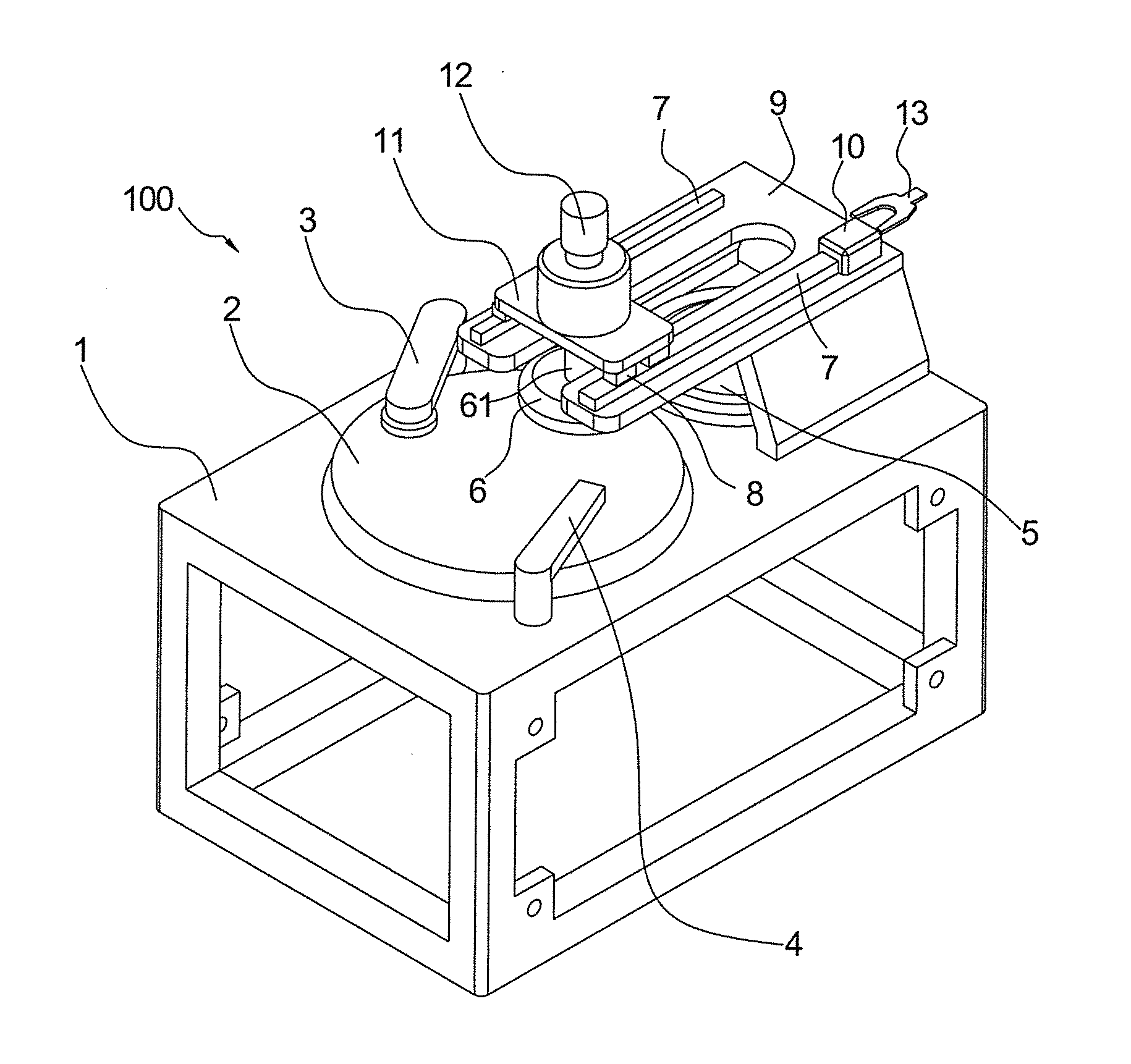
[0021]Referring now to the figures, where like numerals are used to represent like structure, an embodiment of a chemical-mechanical polishing machine according to the invention is generally indicated at 100. As shown in FIG. 1, the chemical-mechanical polishing machine 100 includes generally a work table 1, polishing platen 2, pad conditioner 3, slurry-delivery device 4, loading and unloading table 5, polishing head 6, polishing-head support 9, and robotic manipulator 13.

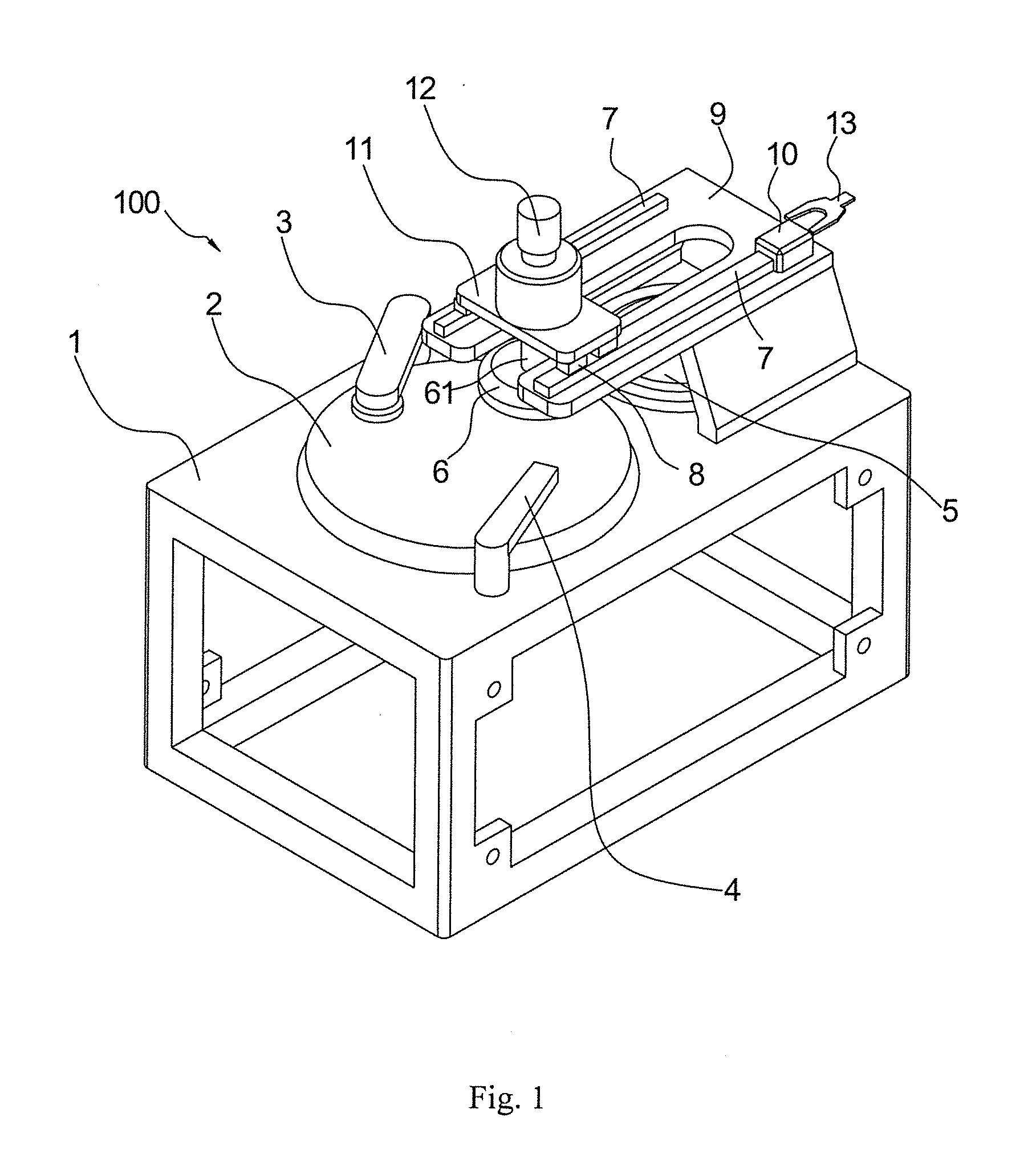
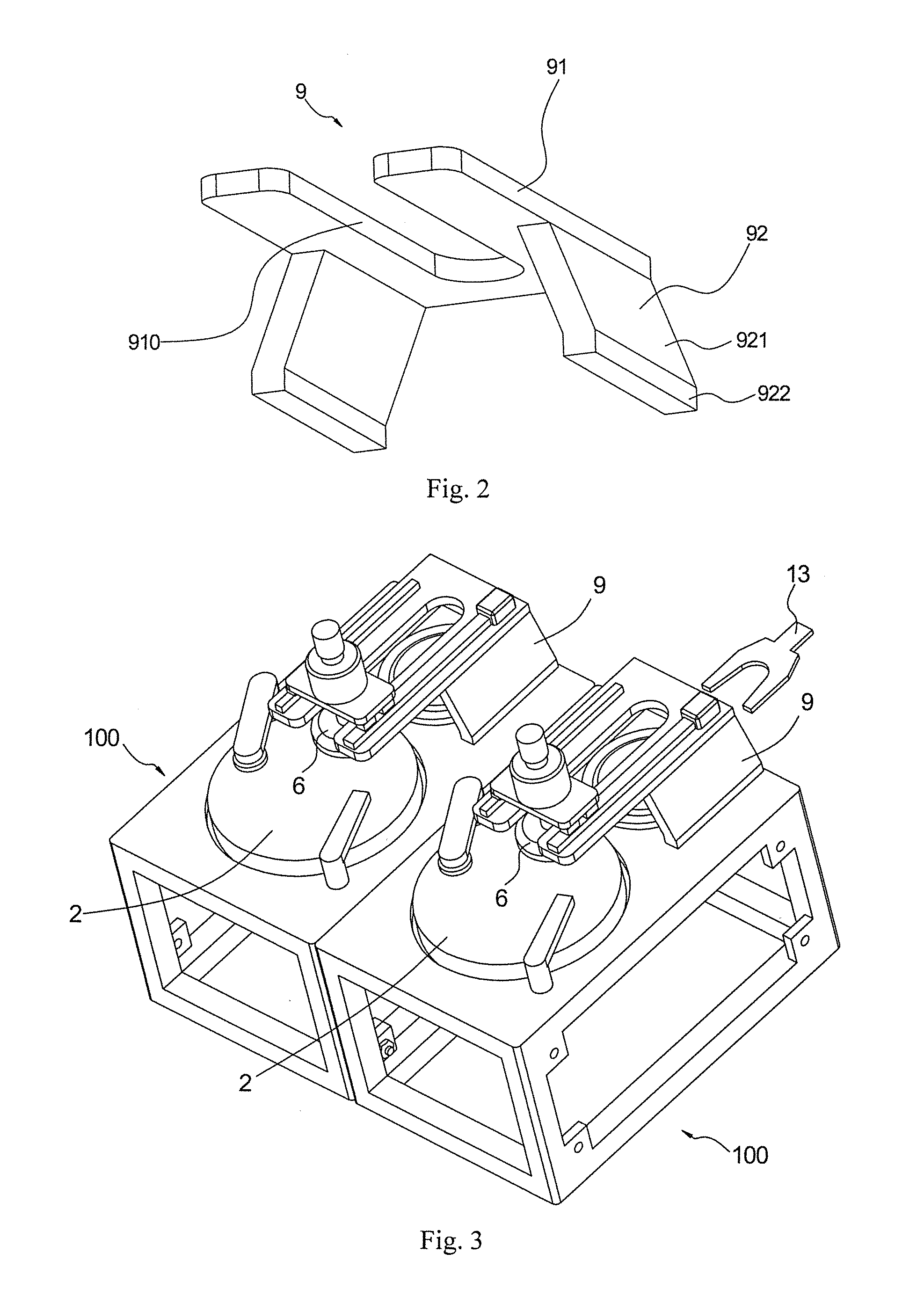
[0022]In an embodiment, as shown in FIGS. 1 and 2, the polishing-head support 9 includes a horizontal base plate 91 and two supporting side plates 92. A groove 910 is formed in the horizontal base plate 91. The groove 910 penetrates through the horizontal base plate 91 along the “thickness” direction of the horizontal base plate 91. The groove 910 is open at one longitudinal end of the horizontal base plate 91 and extends toward the other longitudinal end of the horizontal base plate 91. In other words, one end of ...


PUM


Abstract

A chemical-mechanical polishing machine includes a work table, polishing platen mounted onto the work table, pad conditioner and slurry-delivery device mounted on the work table and disposed near the polishing platen, and polishing-head support mounted on the work table and including a base plate and supporting side plates. The base plate is formed with a groove in a “thickness” direction. A loading and unloading table is mounted on the work table, disposed below the base plate, and opposed to the polishing platen. A polishing head is rotatably disposed on the polishing-head support, movable in the longitudinal direction, and passes through the groove to extend downwardly. A robotic manipulator is disposed near the work table for placing a wafer on the loading and unloading table and taking the wafer away from it. A chemical-mechanical polishing apparatus includes an array of a plurality of the machine.

Description

CROSS-REFERENCE TO RELATED APPLICATIONS[0001]This is “national phase” application of Patent Cooperation Treaty Application PCT / CN2011 / 075452 filed on Jun. 8, 2011, which, in turn, claims priority to and benefit of the filing date of Chinese Patent Applications 201010246628.1 and 201020283455.6 filed on Aug. 5, 2010 and entitled “Chemical Mechanical Polishing Machine and Chemical Mechanical Polishing Apparatus Comprising the Same.”BACKGROUND OF INVENTION[0002]1. Field of Invention[0003]The invention relates, generally, to a chemical-mechanical polishing machine and, more specifically, to a chemical-mechanical polishing apparatus that includes an array of a plurality of the machine.[0004]2. Description of Related Art[0005]During large-scale integrated-circuit manufacturing, the planarization process of the deposition layer on a wafer is necessary and complex. Currently, the planarization process is performed by a chemical-mechanical polishing (CMP), and the chemical-mechanical polishi...

Claims


Application Information

Patent Timeline
Patent Type & Authority Applications(United States)
IPC IPC(8): B24B37/04
CPCB24B37/10B24B37/04
Inventor LU, XINCHUNXU, ZHENJIEHE, YONGYONGWANG, TONGQINGSHEN, PANZHAO, DEWENMEI, HEGENGZHANG, LIANQINGPEI, ZHAOHUILUO, JIANBIN
Owner HWATSING TECH
Why Eureka
Try Eureka