Ink-jet platemaking method

a platemaking and inkjet technology, applied in the field of inkjet platemaking methods, can solve the problems of insufficient printing durability, high cost of exposure devices, and high image formation requirements, and achieve the effects of improving ink gathering, high manufacturing efficiency of ink-jet methods, and high printing durability

Inactive Publication Date: 2011-06-16
KONICA MINOLTA INC
View PDF2 Cites 1 Cited by
  • Summary
  • Abstract
  • Description
  • Claims
  • Application Information

AI Technical Summary

Benefits of technology

[0023]According to the present invention, it was possible to provide an ink-jet plate making method having improved ink gathering caused by coalescence of ink droplets and printing durability which were the problems in the plate making using an ink-jet method, by making use of distinctive features of the convenience and high manufacturing efficiency of an ink-jet method.

Problems solved by technology

However, these methods require extremely high energy for image formation, and an exposure device is also expensive.
However, problems have been noted in that printing durability was insufficient and resolution was decreased due to so-called beading before drying of ink droplets having adhered to the surface of the printing plate.
Therefore, it has the problem of being easy to produce the dot gain phenomenon which transfers even the ink attached to the surrounding of the dots.

Method used


Image

  • Ink-jet platemaking method
  • Ink-jet platemaking method
  • Ink-jet platemaking method

Examples


example 1

>

[0125]A reaction container was charged with 56 g of glycidyl methacrylate, 48 g of p-hydroxybenzaldeyde, 2 g of pyridine, and 1 g of N-nitroso-phenylhydroxyamine ammonium salt, then, the mixture was stirred for 8 hours in a water bath of 80° C.

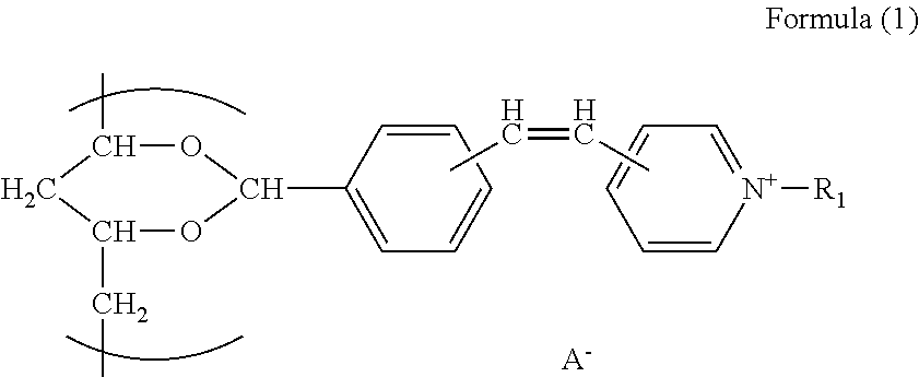
[0126]Subsequently, 45 g of saponified polyvinyl acetate, having a polymerization degree of 300 and a saponification rate of 88%, was dispersed in 225 g of ion-exchanged water, and then 4.5 g of phosphoric acid and p-(3-methacryloxy-2-hydroxypropyloxy)benzaldehyde, having been prepared via the above reaction, were added to the resulting solution in such a manner that the modification rate was allowed to be 3 mol % based on polyvinyl alcohol, then, the mixture was stirred at 90° C. for 6 hours. The thus-prepared solution was cooled to room temperature, and 30 g of a basic ion-exchange resin was added, followed by being stirred for 1 hour. Then, the ion-exchange resin was filtered, and IRUGACURE 2959 (produced by Ciba Specialty Chemicals, Ltd.)...

example 2

>

[0166]Commercially available resin particles J780 (Joncryl 780, made by BASF Co., MFT (water): 89° C., acid value: 46 mg KOH / g), J631 ((Joncryl 631, made by BASF Co., MFT (water): 80° C., acid value: 25 mg KOH / g), NM972 (Nichigo-Mowinyl 972, made by Japanese synthetic-chemistry Co., Ltd., MFT (water): 105° C., acid value: 2 mg KOH / g) each were diluted with ion-exchanged water so that the solid portion became 10%. Then, desalt purification was performed using a small type pump unit of Membrane Master RUM-2 and a thin layer flow flat membrane test cell of Membrane Master C10-T (made by Nitto Denko Co., Ltd.). At this moment, the counter salt was substituted by an amine salt and an alkali metal by adding respectively suitably excessive amounts of an aqueous ammonia solution or alkali metal chloride and ion exchange water. Desalting purification was performed for a sufficient time after adding ammonia or an alkali metal chloride, and each resin particle solution in which the counter sa...


PUM

PropertyMeasurementUnit
boiling pointaaaaaaaaaa

Abstract

An ink-jet platemaking method is provided which takes advantage of the high convenience and high productivity characteristic of platemaking by ink-jet printing and which mitigates or improves the liquid gathering caused by droplet coalescence and printing durability, which have been problematic in platemaking by ink-jet printing. The ink-jet platemaking method comprises: using an ink for platemaking comprising water, one or more water-soluble organic solvents, and fine resin particles; adhering the ink for platemaking to a heated printing plate material; and volatilizing the solvent contained in the platemaking ink to dry the ink and thereby form an image. The ink-jet platemaking method is characterized in that the fine resin particles have a minimum film-forming temperature (MFT (water)) of 40° C. or higher, the ink for platemaking contains a water-soluble organic solvent (A) which lowers the MFT of the fine resin particles by 5° C. or more, the water-soluble organic solvent (A) accounts for 20% or more of all water-soluble organic solvents contained in the ink, and the water-soluble organic solvent (A) has a boiling point of 180-300° C.

Description

TECHNICAL FIELD[0001]This invention relates to an ink-jet palate making method, and specifically, this invention relates to an ink-jet plate making method of a computer to plate (CTP) method using an ink-jet recording method.BACKGROUND[0002]With increased digitization of printing data, it is demanded a CTP method which is cheap and easy to handle, and which has printing aptitude equivalent to a lithographic printing plate (PS plate). Especially in recent years, there have been proposed various types of CTP method using an infra-red laser recording. Among them, so called dry CTP has been taken attention, which does not need a special development process (including a development on a printing press). However, these methods require extremely high energy for image formation, and an exposure device is also expensive.[0003]On the other hand, there was proposed a method in which an oleophilic image was directly formed on a substrate having a hydrophilic surface with an ink-jet method. This...

Claims


Application Information

Patent Timeline
Patent Type & Authority Applications(United States)
IPC IPC(8): B41C3/08B41C1/10B41N1/14C09D11/00C09D11/322C09D11/326C09D11/328C09D11/38G03F7/00
CPCB41C1/1066
Inventor MORITOMO, HITOSHIIIJIMA, HIROTAKAMAEDA, AKIO
Owner KONICA MINOLTA INC
Why Eureka
Try Eureka