

Lamination carrier and lamination method using the same
- Summary
- Abstract
- Description
- Claims
- Application Information
AI Technical Summary
Benefits of technology
Problems solved by technology
Method used
Image

Examples
first embodiment
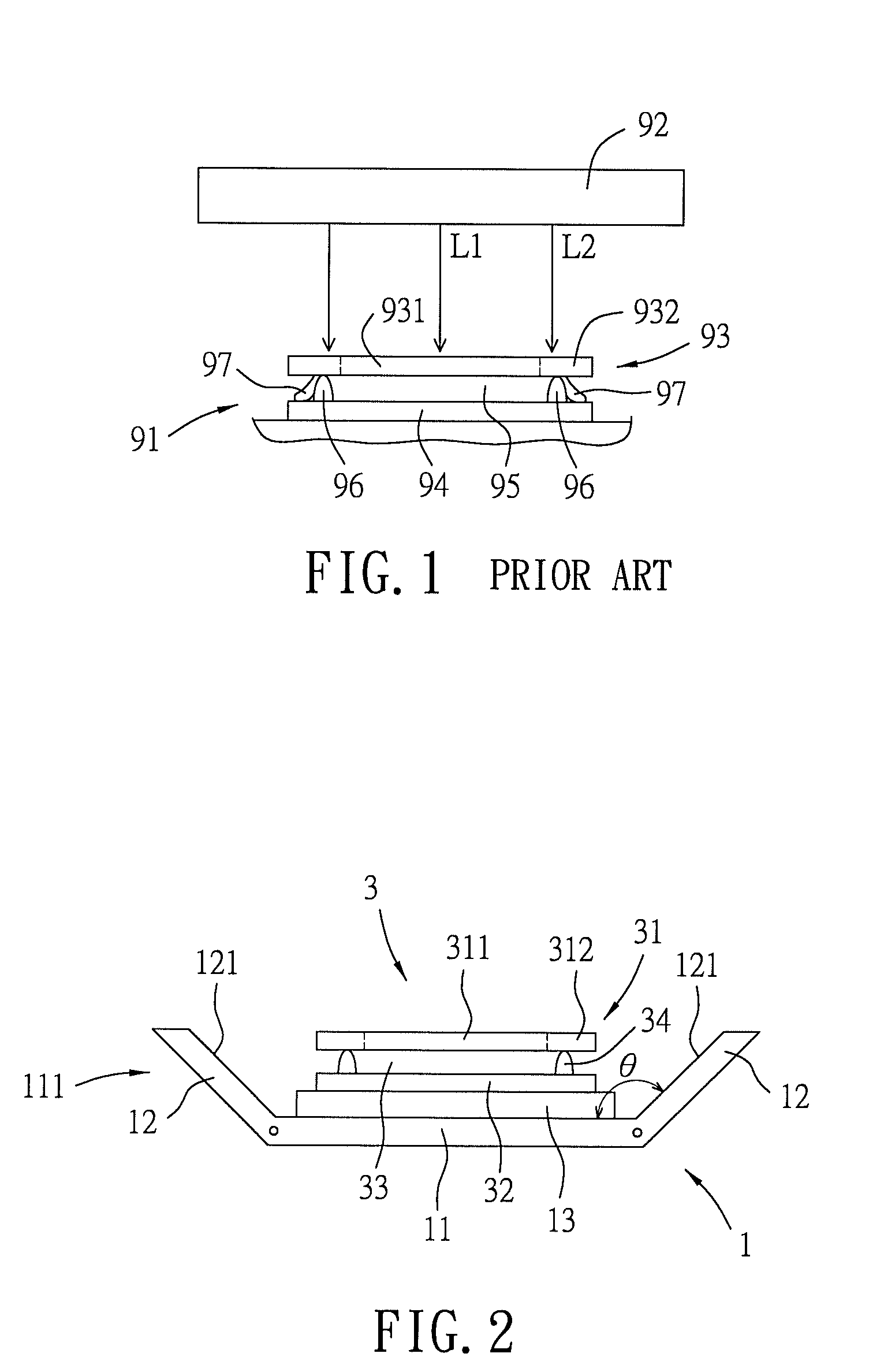
[0024]Referring to FIGS. 2 to 4, the first embodiment of a lamination carrier 1 according to the present disclosure is used together with a lamination device 2 to perform a lamination method of a display device 3.
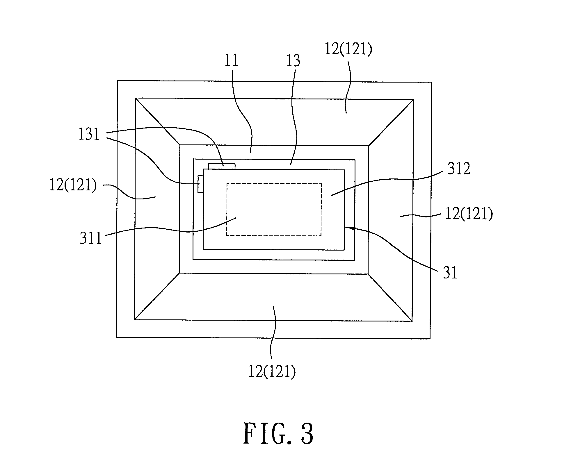
[0025]The structure of the lamination carrier 1 will now be depicted. The lamination carrier 1 includes a base plate 11, a light-guiding structure 111 and a pad 13 disposed on the base plate 11.
[0026]In this embodiment, the base plate 11 is rectangular in shape in order to cooperate with the shape of the display device 3. The light-guiding structure 111 includes four lateral plates 12 that respectively extend upwardly and outwardly from four lateral edges of the base plate 11. The light-guiding structure 111 has four reflecting surfaces 121. It is noted that for simplicity of illustration, only two lateral plates 12 and two reflecting surfaces 121 are illustrated in the drawings other than FIG. 3. Each of the reflecting surfaces 121 is formed on an inner side of a respectiv...
second embodiment
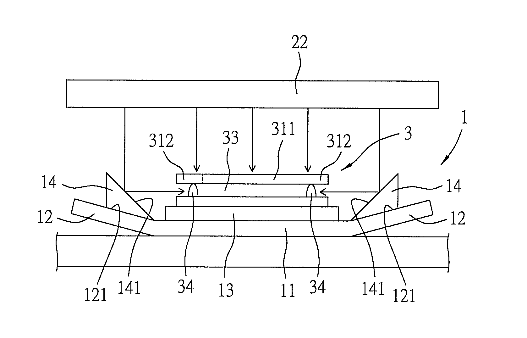
[0039]FIG. 6 illustrates the second embodiment of a lamination carrier 1 according to this disclosure. The lamination carrier 1 has a structure similar to that of the first embodiment, except that the light-guiding structure 111 includes four of the reflecting surfaces 141 and four reflectors 14 that are disposed on the base plate 11 and that are respectively formed with the reflecting surfaces 141. Moreover, the lateral plates 12 are different in arrangement from that of the first embodiment (i.e., the lateral plates 12 are perpendicular to the base plate 11) and are not formed with the reflecting surfaces 121.
[0040]Specifically, in this embodiment, the portion of the light (L5) is directed to and reflected by the reflecting surfaces 141 formed on the reflectors 14 toward the lateral side of the display device 3, i.e., toward the first adhesive layer 33 and the second adhesive layer 34 on the opaque portion 312. Accordingly, in the photo-curing procedure, cooperation of the laminat...
third embodiment
[0042]FIG. 7 illustrates the third embodiment of a lamination carrier 1 according to this disclosure. The lamination carrier 1 has a structure similar to that of the second embodiment, except that the lateral plates 12 are designed to respectively extend outwardly and upwardly from the lateral edges of the base plate 11 and to be respectively formed with reflecting surfaces 121 (i.e., each of the lateral plates 12 has a structure and arrangement similar to those of first embodiment), and that the reflectors 14 are respectively disposed movably and detachably on the lateral plates 12. In this embodiment, since the lateral plates 12 are higher than the base plate 11 in a vertical direction, disposing the reflectors 14 on the lateral plates 12 creates a better ability to adjust the altitude of the reflecting surfaces 141 in comparison with disposing the reflectors 14 on the base plate 11. However, it is noted that, disposition of the reflectors 14 on the base plate 12 is also permissib...
PUM
| Property | Measurement | Unit |
|---|---|---|
| Time | aaaaa | aaaaa |
| Angle | aaaaa | aaaaa |
| Angle | aaaaa | aaaaa |
Abstract
Description
Claims
Application Information