Endoscope system

a technology of endoscope and endoscope, which is applied in the field of endoscope system, can solve the problems of high noise, fine fluctuation, and return light noise, and achieve the effects of removing speckle noise, high efficiency, and appropriately removing nois

Inactive Publication Date: 2013-08-27
FUJIFILM CORP
View PDF15 Cites 1 Cited by
  • Summary
  • Abstract
  • Description
  • Claims
  • Application Information

AI Technical Summary

Benefits of technology

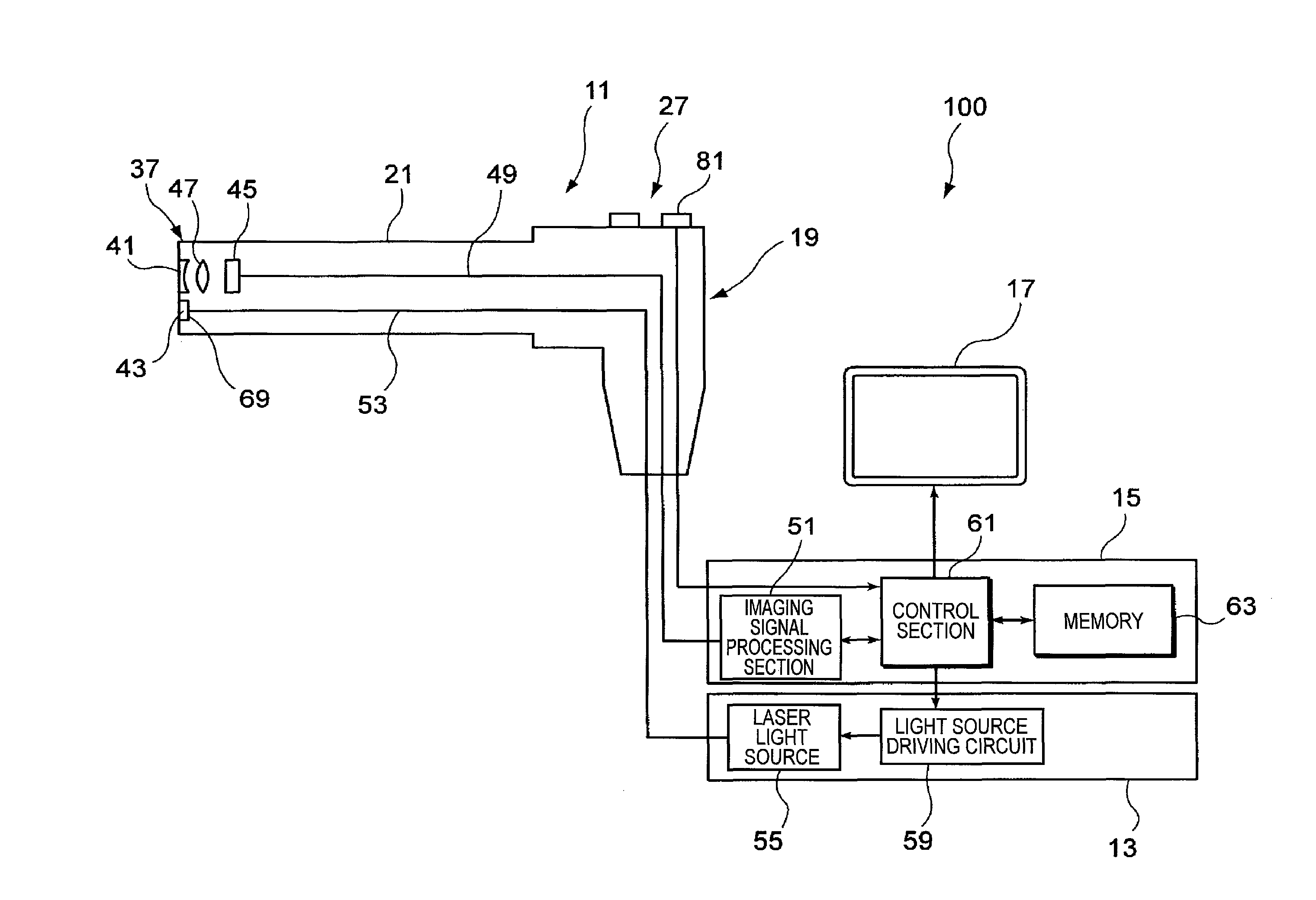
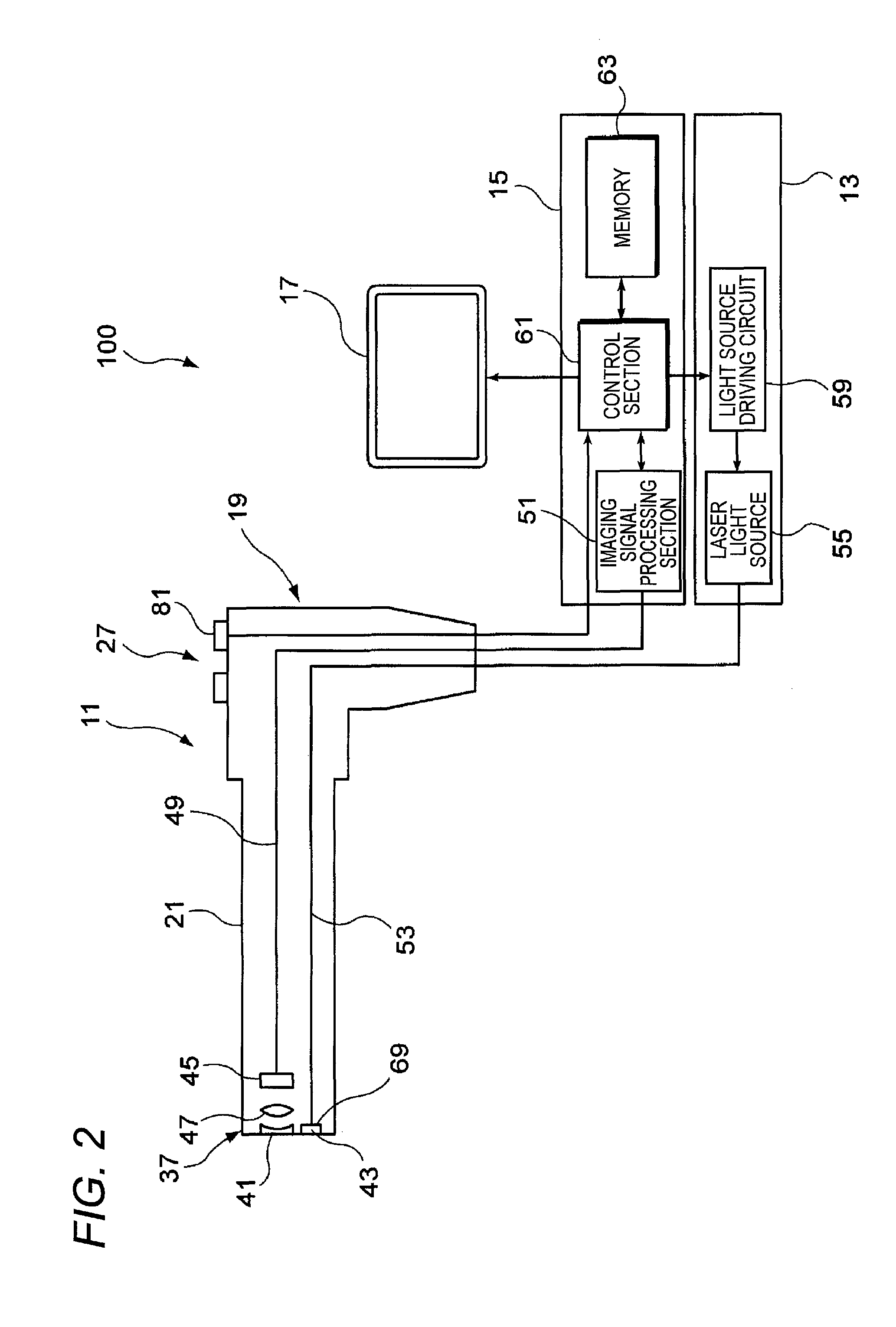
[0009]In the endoscope system, the speckle component is extracted based on the difference information between the first basic color component and the second basic color component, so as to remove the speckle noise by using this speckle component as an evaluation parameter. Therefore, by perform the control using the evaluation parameter with respect to the speckle noise, which has been difficult to quantitatively evaluate, a control amount for removing the speckle noise can be optimally set. Accordingly, it is not necessary to perform useless control or excessive calculation for removing a speckle noise, and hence, the speckle noise can be appropriately removed with high efficiency. As a result, an observation image free from fluctuation and unevenness peculiar to laser can be always stably obtained.

Problems solved by technology

It is known, however, that intensity noises such as a hopping mode noise, a return light noise and a speckle noise on an irradiated face are caused in using a semiconductor laser.
This fine fluctuation is caused due to speckle interference.

Method used


Image

  • Endoscope system
  • Endoscope system
  • Endoscope system

Examples


modification 1

(Modification 1)

[0052]In Modification 1 described below, an imaging device having sensitivities to three basic color components of complementary colors of cyan (C), magenta (M) and yellow (Y) is used for capturing an image.

[0053]The imaging device 45 of this modification has sensitivities to the three basic color components of C, M and Y. The color components of C, M and Y are respectively expressed by expressions (1), (2) and (3) below using three basic colors of primary colors RGB. Each of the C component and the M component includes a B (blue) component on which a speckle noise component Bs is superimposed. Therefore, in an image, captured by the imaging device, of a subject under the white illumination light including the laser beam, the speckle noise component Bs is superimposed in the C component and the M component as illustrated in FIG. 6.

C=B+G   (1)

M=B+R   (2)

Y=G+R   (3)

[0054]In order to extract the speckle noise component Bs from these C, M and Y basic color components, th...

modification 2

(Modification 2)

[0057]In Modification 2 described below, an imaging device having sensitivities to four basic color components of C, M, Y and G is used for capturing an image.

[0058]The imaging device 45 of this modification has sensitivities to the four basic color components of C, M, Y and G When the imaging device 45 of this modification is used, captured images of C, M, Y and G components are obtained as illustrated in FIG. 7, and a speckle noise component Bs is superimposed on the C and M components as described in Modification 1.

[0059]In this modification, B and G components may be obtained in accordance with the expressions (4) and (5) using the C, M and Y components in the same manner as in Modification 1. Since the G component is known, however, a simpler process may be employed in this modification. Specifically, the imaging signal processing section 51 obtains a B component by using the known G component in accordance with the following expression (8):

B=C−G   (8)

[0060]Then...


PUM


Abstract

An endoscope system is able to stably obtain an image free from speckle interference. A captured image including a first basic color component B on which a speckle noise of a laser beam is superimposed and a second basic color component G not including the speckle noise. A speckle noise component Bs is extracted based on difference information between the first basic color component B and the second basic color component G Based on the extracted speckle noise component Bs, the speckle noise component Bs is removed from the first basic color component B, so as to obtain a good observation image free from the speckle noise.

Description

CROSS-REFERENCE TO RELATED APPLICATIONS[0001]This application claims the benefit of Japanese Patent Application No. 2010-146865, filed Jun. 28, 2010, the entire contents of which are hereby incorporated by reference, the same as if set forth at length.BACKGROUND OF INVENTION[0002]1. Field of the Invention[0003]The present invention relates to an endoscope system.[0004]2. Description of the Related Art[0005]In an endoscope system widely used, light emitted from a lamp provided in a light source device is guided by a light guide provided along an endoscope inserting section, and illumination light thus guided by the light guide is emitted through an illumination window disposed at a tip of the endoscope inserting section for irradiating an examination target site. On the contrary, a laser light source is used instead of the lamp for the illumination in some endoscope systems. For example, in a lighting apparatus described in JP 2005-205195 A, light emitted from a blue semiconductor la...

Claims


Application Information

Patent Timeline
Patent Type & Authority Patents(United States)
IPC IPC(8): A61B1/06A61B1/04
CPCA61B1/05A61B1/0653A61B1/07G02B27/48G06T5/002G02B23/2469G06T2207/10068G06T2207/10024
Inventor KURODA, OSAMUIIDA, TAKAYUKI
Owner FUJIFILM CORP
Why Eureka
Try Eureka