System and method for demultiplexing optical multi-wavelength signals

a multi-wavelength signal and optical multi-wavelength technology, applied in multiplex communication, optical elements, instruments, etc., can solve the problems of large footprint, high power consumption and dissipation, and the practical impossibility of consolidating the entire demultiplexing arrangement into a single photonic integrated circuit, so as to reduce the impact of noise and other transmission impairments on the reception process, and the effect of high reception sensitivity

Inactive Publication Date: 2013-08-27
WSOU INVESTMENTS LLC
View PDF6 Cites 0 Cited by
  • Summary
  • Abstract
  • Description
  • Claims
  • Application Information

AI Technical Summary

Benefits of technology

[0009]However, the current trend in manufacturing photonic devices points towards opposite requirements, namely minimizing the footprint and the power consumption of the overall device, as well as simplifying as much as possible the integration of such components in a integrated circuit.
[0012]Each delay filter then outputs the main constituent S1a, S2a, . . . , SNa at one output port and the complementary constituent S1b, S2b, . . . , SNb at another output port. The main and complementary constituents are then detected by respective pair of photodiodes 12Xa-12Xb, (X=1 . . . N). It is to be noted that in practice, the complementary constituents of the signal may simply be ignored and the main signal be maintained for further processing. This is useful because using differential detection allows for a higher reception sensitivity which can reduce the impact of noise and other transmission impairments on the reception process.

Problems solved by technology

As a consequence of requiring a plurality of discrete elements, conventional demultiplexers would require a relatively large footprint and a relatively high power consumption and dissipation, which is undesired.
Another drawback of using such discrete elements resides in the difficulty, or even practical impossibility of consolidating the entire demultiplexing arrangement into a single photonic integrated circuit.
Also the integration of such an arrangement into a photonic integrated circuit would be a complicated task.
Also the integration of such arrangement into a photonic integrated circuit would also be a complicated task.

Method used


Image

  • System and method for demultiplexing optical multi-wavelength signals
  • System and method for demultiplexing optical multi-wavelength signals
  • System and method for demultiplexing optical multi-wavelength signals

Examples


Embodiment Construction

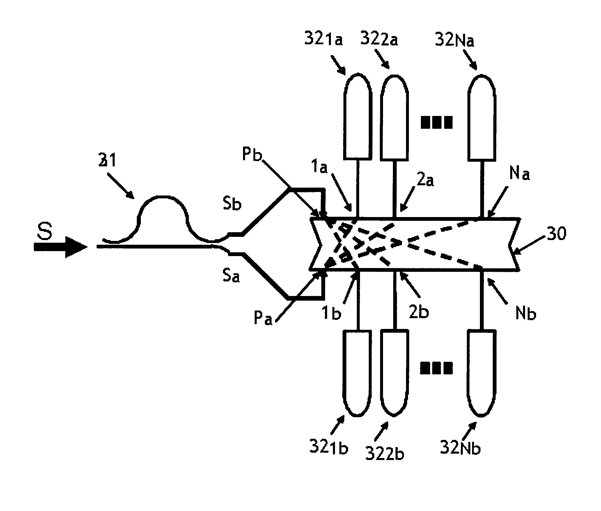
[0048]According to embodiments of the invention, a multi-input port and multi-output frequency demultiplexer is used in a bi-directional scheme so as to provide a demultiplexing functionality of two streams of multiple wavelengths.

[0049]By way of non-limiting examples a frequency demultiplexer to be used in the solution provided herein may be array waveguide gratings (AWG) and echelle gratings which are known and available in the market. In the following description, array waveguide grating in discussed in the description of embodiments. However other frequency demultiplexers may also be used within the scope of the embodiments.

[0050]One exemplary embodiment is shown in FIG. 3a which is provided in relation to QPSK WDM wavelengths. As shown in the figure, an input signal S, comprising optical wavelengths modulated with QPSK format, is input into a delay filter 31 which separates the received signals into two streams Sa and Sb corresponding to the main constituent and the complementa...


PUM


Abstract

A demultiplexer and a method of demultiplexing a multiplex of spatially separable multiple wavelength streams, where an incoming multiplex of multiple wavelength streams is separated into a first stream of wavelengths and a second stream of wavelengths according to at least one predetermined separation criterion. The first stream and the second stream are respectively input into a first and a second input port of a multi-input port, multi-output port frequency demultiplexer where the first stream and the second stream are separated into a first group of single wavelengths and a second group of single wavelengths respectively. The first group of single wavelengths is coupled to respective output ports and the second group of single wavelengths are coupled to respective output ports.

Description

[0001]This application is based on and claims the benefit of the European patent application number 09305492.2, filed on May 28, 2009 the content of which is incorporated by reference herein in its entirety.[0002]The present invention relates to demultiplexing optical multi-wavelength signals corresponding to any transmission format that comprises multiple wavelengths where the wavelengths comprise constituents that can be separated into distinct streams or detected according to differential detection schemes.BACKGROUND OF THE INVENTION[0003]Optical multi-wavelength signal transmissions are widely used for communication through optical networks. One example of such transmission is the Wavelength Division Multiplex (WDM) transmission where signals are transported by a plurality of optical carriers. In certain types of such transmission, some or all of individual optical carriers may transport signals comprising multiple streams that can be separated into distinct multiple sub-streams...

Claims


Application Information

Patent Timeline
Patent Type & Authority Patents(United States)
IPC IPC(8): H04J14/02
CPCH04J14/02G02B6/12019H04B10/66G02B6/34
Inventor BERNASCONI, PIETRO
Owner WSOU INVESTMENTS LLC
Why Eureka
Try Eureka