
Wear part device for a work tool

a wear part and work tool technology, applied in the direction of harrows, drags, ploughs, etc., can solve the problems of loss of the benefit of a replaceable wear part, the wear part holder is exposed to as much wear as the wear part itself, etc., to achieve sufficient effect on the working life of the wear part, improve the use of the wear part material, and improve the material flow

Active Publication Date: 2013-09-10
KVERNELAND GROUP OPERATIONS NORWAY
View PDF8 Cites 10 Cited by
  • Summary
  • Abstract
  • Description
  • Claims
  • Application Information

AI Technical Summary

Benefits of technology

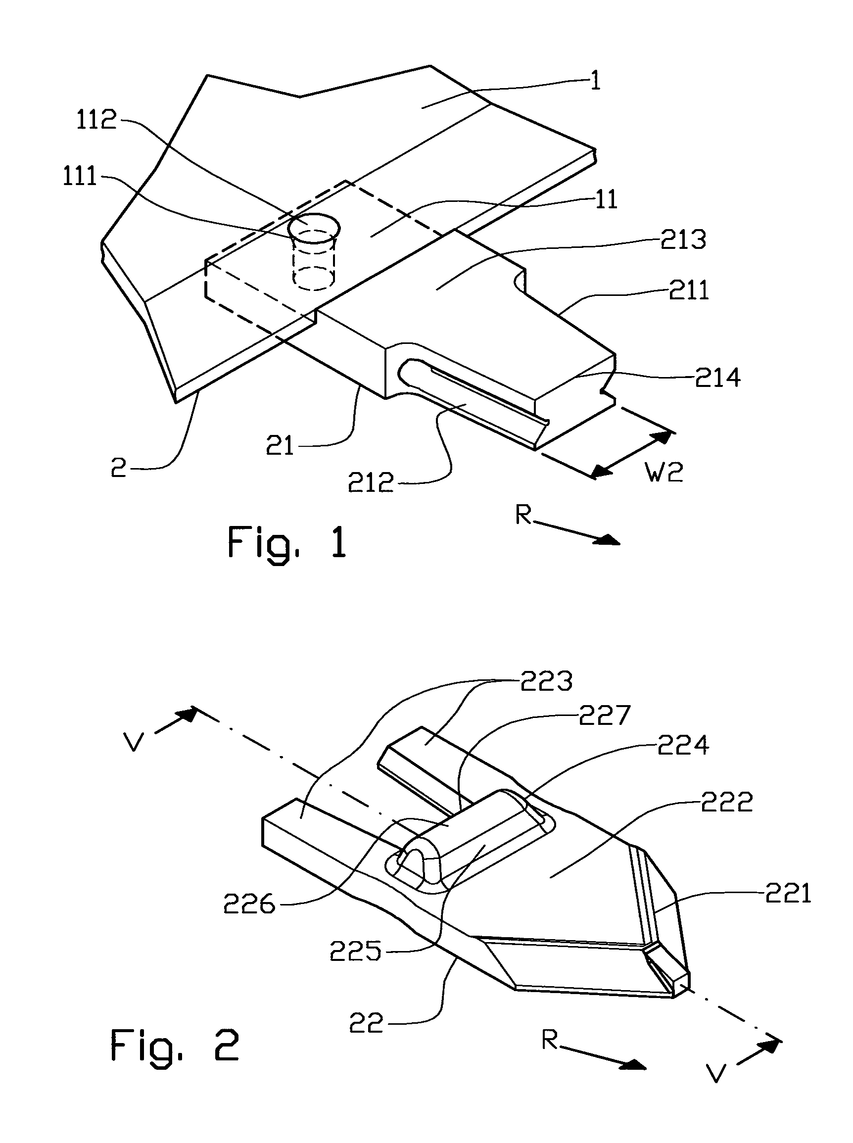
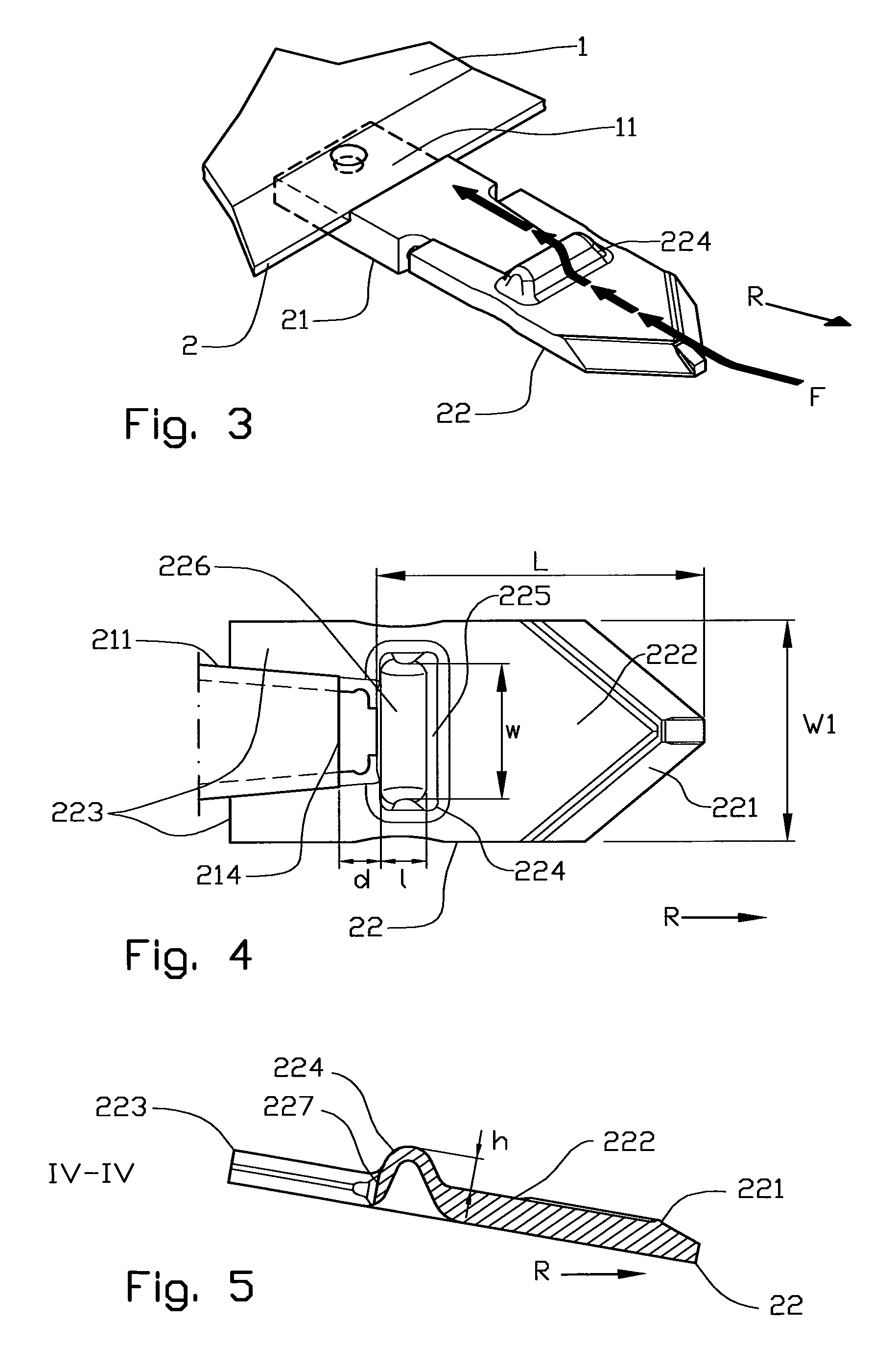
The patent is about a new design for a wear part holder and wear part that increases the working life of the wear part without impairing its performance. This is achieved through a ridge on the ridge part of the wear part holder that redirects the material flow away from the sliding surfaces and interconnecting parts, reducing wear. The ridge is also designed to be cross-wise, which improves material flow and protection of the wear part and holder. Additionally, the ridge has a front surface tilting in the direction of movement, further improving material flow. The ridge is at least 10 mm high, which provides enough material to the wear part holder without impacting the material flow. Overall, this design increases the durability of the wear part and reduces downtime for maintenance.

Problems solved by technology

It has turned out that on some types of tools, such as ploughs and cultivators, said wear part holder is exposed to as high wear as the wear part itself.
In such situations the benefit of a replaceable wear part is lost by the very fact that the wear part and the wear part holder has the same working life and must be replaced simultaneously.

Method used


Image

  • Wear part device for a work tool
  • Wear part device for a work tool
  • Wear part device for a work tool

Examples


Embodiment Construction

[0021]Referring now to the drawings in the following, there will now be described preferred embodiments of a replaceable wear part of the invention adapted for fitting on a work tool having one or more, working forward edges or fronts arranged to be able to work in a specific material, and which is exposed to wear over time.

[0022]The preferred embodiment examples being described are associated with earth working tools for use in agriculture, but it is to be understood that the invention has further application, as it may be used on replaceable working blades of per se known kind, and for other types and combinations of working tools requiring fitting of replaceable working blades held on by a wear part holder whose working life is desired prolonged.

[0023]On a working tool 1 is formed an attachment portion 11 for a replaceable forward edge element 2. The edge element 2 may be formed as a blade or shear on a plough or as a leveling blade, a jaw on an excavator bucket, an end portion o...


PUM


Abstract

A replaceable wear part device for attachment on a forward edge of a work tool includes at least a portion of the forward edge of the work tool that has an attachment section having spaced engagement surfaces. The wear part device has a complimentary attachment section provided with spaced engagement surfaces in which the respective engagement surfaces may mutually and slidably engage to hold the wear part device attached to the work tool. The wear part device has an elongated eminence arranged crosswise to the intended operating direction of the work tool, and immediately forward of the attachment section of the wear part. The eminence extends laterally across a first sliding surface by a distance at least equal to a distance between the mutually engaged engagement surfaces.

Description

FIELD OF THE INVENTION[0001]The invention relates to a replaceable wear part device for attaching to the forward edge of a work tool, where at least a portion of the forward edge is formed by a wear part holder, as the wear part is provided with a first sliding surface, and the wear part holder is provided with a second sliding surface, which is essentially arranged as an extension of said first sliding surface, and the second sliding surface is provided with a forward sliding edge surface defining the sliding surface against the wear part, more particularly by an eminence on the first sliding surface arranged to be able to lead a material flow away from at least a portion of the wear part holder's sliding surface.BACKGROUND[0002]From work tools provided with an edge, rim, prong, tooth or the like arranged to be able to work against and move uncompacted material such as earth, gravel, pebbles etc., it is known to use replaceable wear parts to increase the working life of the portion...

Claims


Application Information

Patent Timeline
IPC IPC(8): E02F9/26
CPCE02F9/2858E02F9/2825
Inventor SKJ.AE BUTTED.VELAND, MAGNE
Owner KVERNELAND GROUP OPERATIONS NORWAY
Learn More