Position detection

a technology of position detection and detection mode, applied in the field of position detection, can solve the problems of inability to easily increase, limited accuracy and resolution, and the most sensitive to radiation of electronics, and achieve the effect of fast and accurate control of the mirror position

Active Publication Date: 2013-09-17
ELEKTA AB
View PDF17 Cites 31 Cited by
  • Summary
  • Abstract
  • Description
  • Claims
  • Application Information

AI Technical Summary

Benefits of technology

[0013]The scanning light source can comprise a source of light that illuminates a mirror, the mirror being controllably adjustable so as to direct a reflected beam of light in a scan pattern. The mirror is preferably part of a micro-electromechanical (“MEMS”) device, so as to allow swift and accurate control of the mirror position.
[0014]The reflective objects are preferably fixed, so that the return signal that they produce when illuminated can occur at a fixed point in the scan cycle, making it straightforward to identify a return signal corresponding to a reflective element.
[0015]At least one other mirror is preferably located (or locatable) in the radiation beam path, to permit the scanning light source to be located out of the beam path thereby protecting it from incident radiation.
[0020]Tracking objects using MEMs mirrors and laser light is known, for example from U.S. Pat. No. 7,498,811 or from “Fast and high-precision 3D tracking and position measurement with MEMs micromirrors” Milanovic, V. & Wing, Kin Lo, IEEE / LEOS International Conference on Optical MEMs and Nanophotonics, 2008 (pp 72-73). However, it does not appear to have been applied to the detection of leaf positions in an MLC array. The Milanovic system also needs to interrogate the MEMS driver in order to ascertain the position of the mirror at the instant when the signal is detected or reflected. By placing reflective objects at known locations within the region and / or reflective elements on the moving object, the complexity and the cost of the system is reduced, and the accuracy of the system is improved, and multiple object positions (such as MLC leaves) can be tracked within the laser scanning field of view. In addition, placing so-called “boundary markers” allows the system to determine the object position relative to the boundary markers using simple algorithms based on the signal time measurements, and avoids the need to interrogate the MEMS driver. The reflective objects need not be at the actual boundaries of the region, although that is likely to be particularly straightforward to implement.

Problems solved by technology

One particularly difficult context is in tracking the positions of individual leaves of a multi leaf collimator (MLC) in a linear accelerator (Linac).
The main problem with such systems is that the accuracy and resolution are limited by the number of pixels within the camera.
This cannot be easily increased.
In addition, most electronics (including CCTV cameras) are susceptible to radiation, and will eventually break down if exposed to significant levels.
Radiation hardened cameras can be designed, but these are expensive and are usually bespoke, so are not readily available.
Where fast movements are required of the MLC leaves, this frame rate may not be adequate to keep up.
Video processing software is also required, which is computationally demanding and therefore increases system complexity and cost.
The CCTV camera is bulky, and needs to be fitted into an area where space is at a premium.
Electromagnetic noise generated from within the Linac can interfere with the image quality and may interfere with the image processing software, causing a loss of leaf positions.
Other contexts exist in which similar problems are encountered, however.
Finally, CCTV cameras are responsive to a broad range of optical wavelengths, making them susceptible to sources of interference such as room lasers, fluorescent lights, and the like.

Method used


Image

  • Position detection
  • Position detection
  • Position detection

Examples


Embodiment Construction

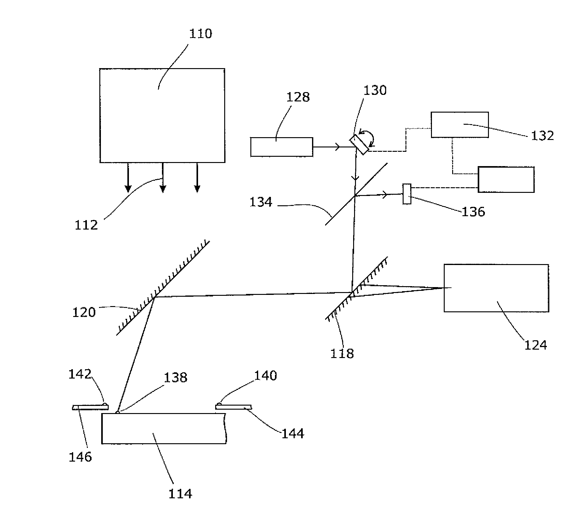
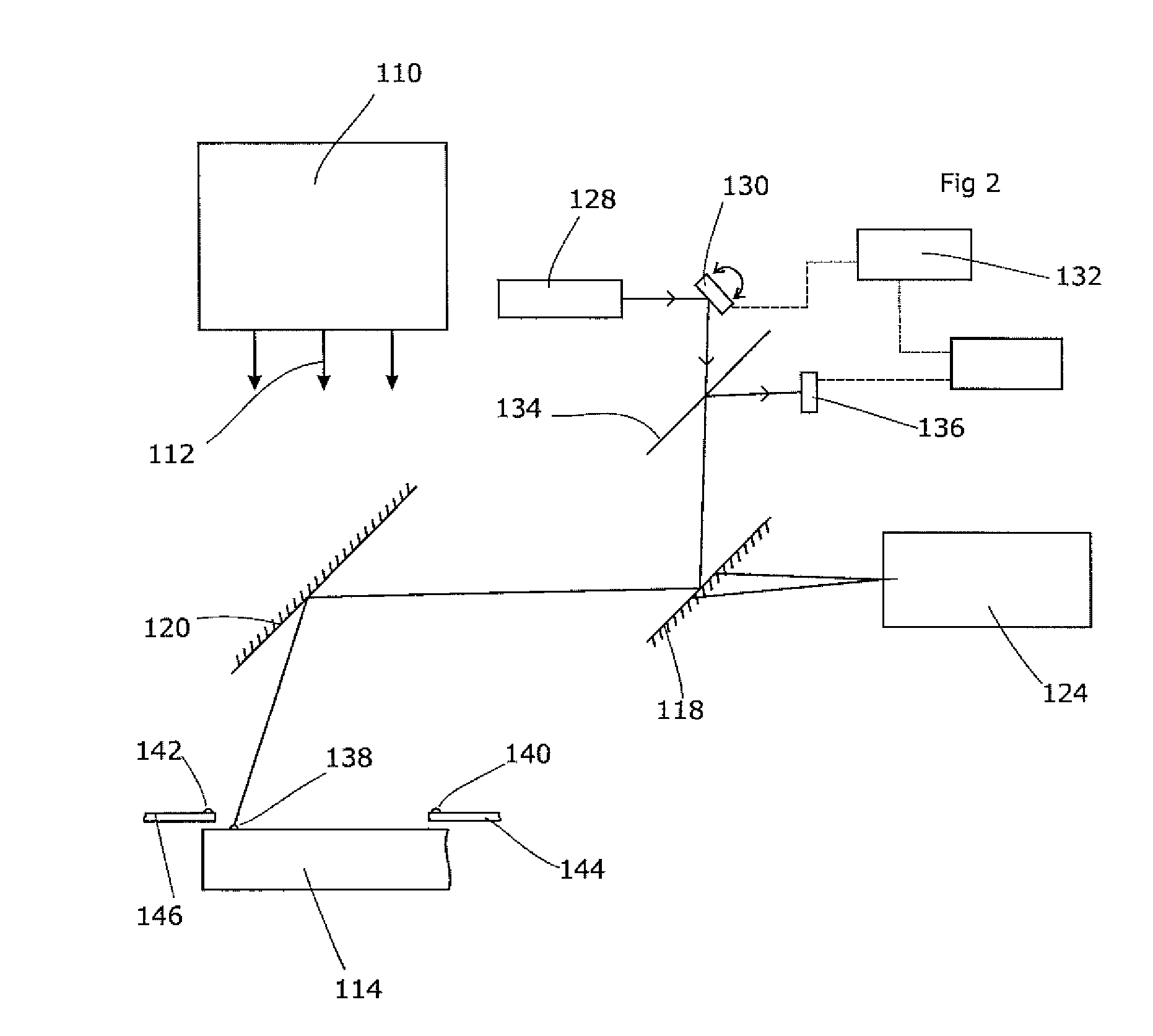
[0027]The following embodiment of the present invention is a position-detection system for the leaves of a multi-leaf collimator. This faces significant difficulties as set out above, which are alleviated by the present invention. However, the invention is also applicable in other contexts.

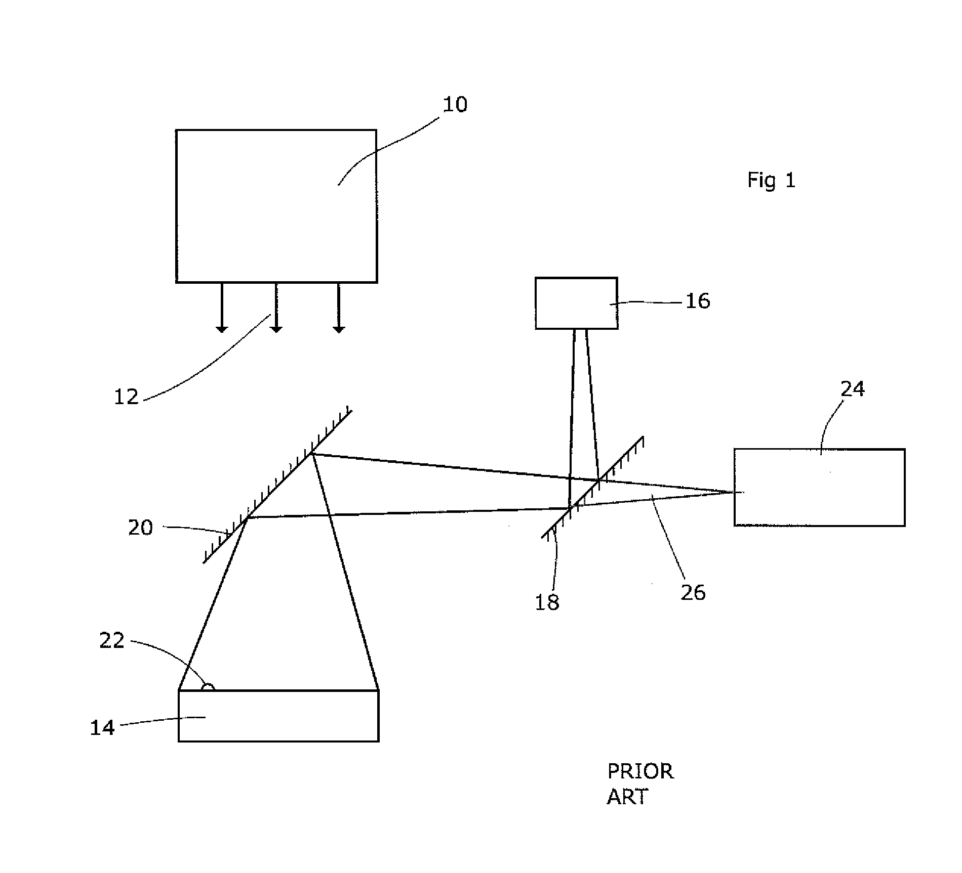
[0028]FIG. 1 shows a known position tracking system for an array of MLC leaves. A radiation source 10 emits a beam of radiation 12 towards a treatment volume, illustrated (by convention) as being in a downward direction. In practice, the source is usually rotated around the treatment volume so as to irradiate the region of interest from a range of different angles, thereby reducing the irradiation of surrounding tissue.

[0029]The shape of the radiation beam 12 is collimated by an MLC comprising an array of individual leaves 14. These are deep in the beam direction, elongate, and narrow in width. They are arranged side-by-side, and are individually moveable back and forth, into and out of the beam. ...


PUM


Abstract

Apparatus for location-detection of an object within a region comprising a reflective element mountable on the object, a scanning light source adapted to issue a beam of light in a scanning pattern illuminating a point that moves over the region, a detector for light reflected from the reflective element and a control unit adapted to report the position of an object based on the point in the scanning pattern at which the detector detects light returned from the reflective element relative to at least one point in the scanning pattern at which the detector detects light returned from a reflective object.

Description

CROSS REFERENCE TO RELATED APPLICATIONS[0001]This application is a continuation-in-part application of International Application No. PCT / EP2010 / 001265, filed Mar. 2, 2010 and published as WO 2011 / 107111 A1 on Sep. 9, 2011, the content of which is hereby incorporated by reference in its entirety and a continuation-in-part of Application No. PCT / EP2010 / 001266, filed Mar. 2, 2010 and published as WO / 2011 / 107112 A1 on Sep. 9, 2011, the content of which is hereby incorporated by reference in its entirety.FIELD OF THE INVENTION[0002]The present invention relates to an improved form of position detection. It is especially (but by no means solely), suitable for the detection of leaf positions in a Multi-Leaf Collimator (“MLC”) for use in radiotherapeutic apparatus.BACKGROUND ART[0003]There are a wide range of contexts in which it is necessary to determine the position of a remote object. One particularly difficult context is in tracking the positions of individual leaves of a multi leaf col...

Claims


Application Information

Patent Timeline
Patent Type & Authority Patents(United States)
IPC IPC(8): G01B11/14G21K1/04
CPCG01S17/42G01S17/10G01S7/4817G21K1/046A61N5/1045
Inventor HUMPHREY, MALCOLM
Owner ELEKTA AB
Why Eureka
Try Eureka