Packages for high power operation of optical fiber components

a technology for optical fiber components and packaging, applied in the direction of paper/cardboard containers, lamination, containers, etc., can solve the problems of splicing to burn or melt, putting a strain on the power handling capabilities of laser components, and more absorption

Active Publication Date: 2013-09-24
CORACTIVE HIGH TECH
View PDF23 Cites 35 Cited by
  • Summary
  • Abstract
  • Description
  • Claims
  • Application Information

AI Technical Summary

Problems solved by technology

More and more, these applications require the laser to emit at the kilowatt power level which puts a strain on the power handling capabilities of laser components.
In turn, the resulting excessive heating may cause thermal degradation to the fiber's low index polymer 3 and to the acrylate protective jacket 4, rendering them even more absorptive to light, ultimately causing the splice to burn or melt and triggering a catastrophic failure of the fiber laser.
Another common mode of failure in fiber lasers occurs in the first few centimeters of the amplifying fiber after the entry point of the pump power.
In the doped fiber core, quantum defect result in pump radiation being converted into heat in the glass host matrix.
The adhesive bonds are made of a material that has high transparency in damp heat as well as a high glass transition temperature and is capable of withstanding temperatures of over 100° C. However, the proposed adhesives in Wetter et al. are poor thermal conductors, which can cause thermal degradation and failure.
However, to the knowledge of the inventor, adhesive material that is simultaneously a good thermal conductor and optically transparent is not currently available.

Method used


Image

  • Packages for high power operation of optical fiber components
  • Packages for high power operation of optical fiber components
  • Packages for high power operation of optical fiber components

Examples


Embodiment Construction

[0054]The present invention will be described more fully hereinafter with reference to the accompanying drawings, and more specifically with reference to FIGS. 4A to 8B, in which like numerals refer to like elements throughout.

[0055]It will be understood by one skilled in the art that the embodiments below are given by way of example only and that the characteristics given are in no way limitative to the scope of the present invention.

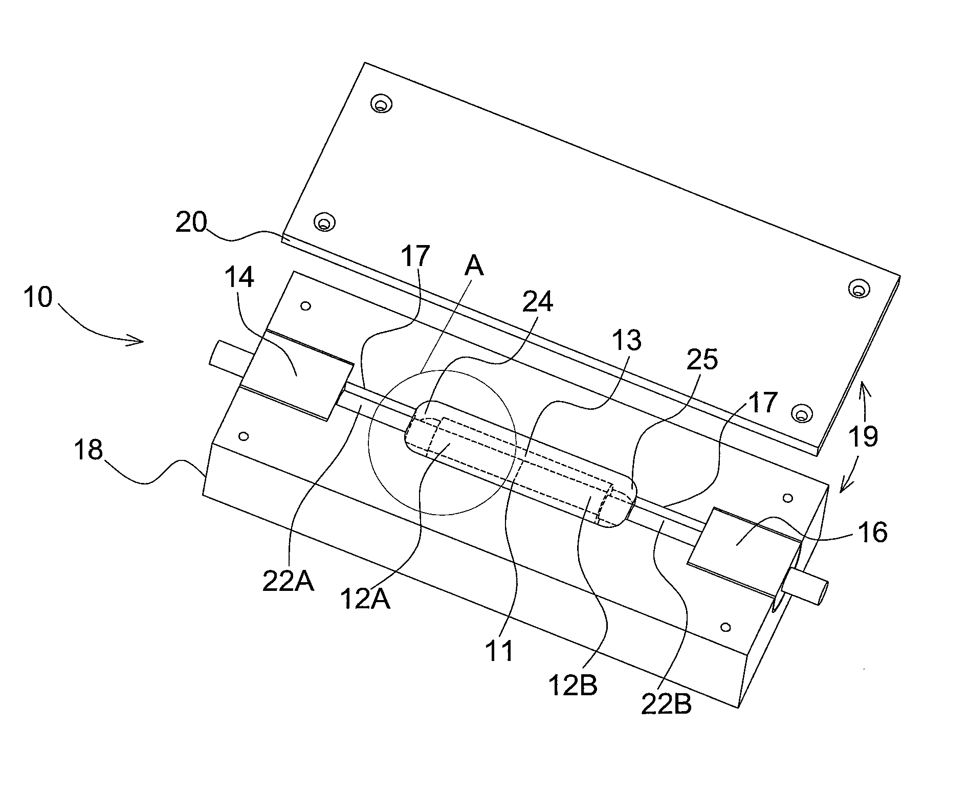
Package for Optical Fiber Component

[0056]Referring to FIGS. 4A to 8B, the present invention provides a package 10 for dissipating at least one of heat power or optical power from an optical fiber component of a device to advantageously prevent or limit degradation of the optical fiber component and thereby maintain overall performance of the component and device.

[0057]Throughout the present application, the term “power” is understood to refer generally to the rate at which energy is transmitted. Heat is the transfer of energy from one body or system to...


PUM

PropertyMeasurementUnit
temperatureaaaaaaaaaa
temperaturesaaaaaaaaaa
refractive indexaaaaaaaaaa

Abstract

A package for dissipating heat power and / or optical power from an optical fiber component of a device is provided. The package includes a heat sink packaging receptacle for accommodating the optical fiber component having a cavity for receiving a temperature sensitive portion of the optical fiber component. According to one aspect, the package may include a power-dissipative material for dissipating heat power or optical power, the power-dissipative material extending within the cavity and surrounding the temperature-sensitive portion of the optical fiber component. According to another aspect, the package may include at least one channel extending between the cavity and an end of the heat sink packaging receptacle, the channel being in intimate contact with the cladding of the optical fiber component for dissipating heat power and / or optical power from the optical fiber component.

Description

RELATED APPLICATIONS[0001]This application is the U.S. National Phase under 35 U.S.C. §371 of International Application No. PCT / CA2009 / 000889, filed on Jun. 25, 2009, which in turn claims the benefit of U.S. Application No. 61 / 075,473, filed on Jun. 25, 2008, the disclosures of which Applications are incorporated by reference herein.FIELD OF THE INVENTION[0002]The present invention relates to packages for optical fiber components. More particularly, it relates to packages for dissipating at least one of heat power or optical power from an optical fiber component of a device.BACKGROUND OF THE INVENTION[0003]Fiber lasers are becoming the laser of choice in numerous industrial applications. More and more, these applications require the laser to emit at the kilowatt power level which puts a strain on the power handling capabilities of laser components. A key element of this revolution, is the development of double clad optical fibers (DCOF), presented in FIG. 1. These fibers serve as br...

Claims


Application Information

Patent Timeline
Patent Type & Authority Patents(United States)
IPC IPC(8): G02B6/00
CPCG02B6/3636H01S3/06704G02B6/243G02B6/14G02B6/0218G02B6/2558Y10T156/10G02B6/4296H01S3/042Y10T29/49826
Inventor CHATIGNY, STEPHANE
Owner CORACTIVE HIGH TECH
Why Eureka
Try Eureka