
Rig mat system and method of making the same

a technology of rig mats and rigs, applied in the field of rig mat systems, can solve the problems of reducing the shear strength of the structure, affecting the service life of the rig mat, and not providing substantial thermal or reflective insulation valu

Inactive Publication Date: 2013-10-01
STRAD ENERGY SERVICES
View PDF13 Cites 19 Cited by
  • Summary
  • Abstract
  • Description
  • Claims
  • Application Information

AI Technical Summary

Benefits of technology

The system provides enhanced thermal insulation, complete spill containment, and a stable working surface, reducing environmental impact and extending the drilling season by maintaining terrain integrity.

Problems solved by technology

The service of rig mats can be severe including the support of heavy loads including dynamic loads of wheeled and tracked vehicular traffic.
Generally rig mats do not provide any substantial thermal or reflective insulation value.
Arrangements which require interconnected panels, even with an insulating core, have inherent problems due to gaps, both physical gaps and increased thermal conductivity, caused by the structural interconnecting points between panels, defeating the insulation provided by the foam filled cores.
There are also problems with effectively bonding foam to the skins of an insulated core which reduces the shear strength of the structure.
Further, the physical gaps between panels are pathways for spills to the ground, substantially any spill being undesirable.
Water and other undesirable fluids can seep through such gaps and contaminate the ground below the rig mat.
The remediation itself comes with an environmental cost for equipment, consumables and fuel.
One form of remediation is to steam clean the gravel after each drilling operation which involves transporting the gravel to a steam cleaning plant which is a cumbersome task in the Arctic and other remote areas typical of drilling operations.

Method used


Image

  • Rig mat system and method of making the same
  • Rig mat system and method of making the same
  • Rig mat system and method of making the same

Examples


Embodiment Construction

[0030]Herein, embodiments are directed to a rig mat system comprising a barrier layer between a plurality of interconnected rig mat panels and a terrain on which the assembled rig mat is located. Accordingly, regardless of any liquid or heat seeping through the rig mat such liquid or heat is prevented from reaching the terrain.

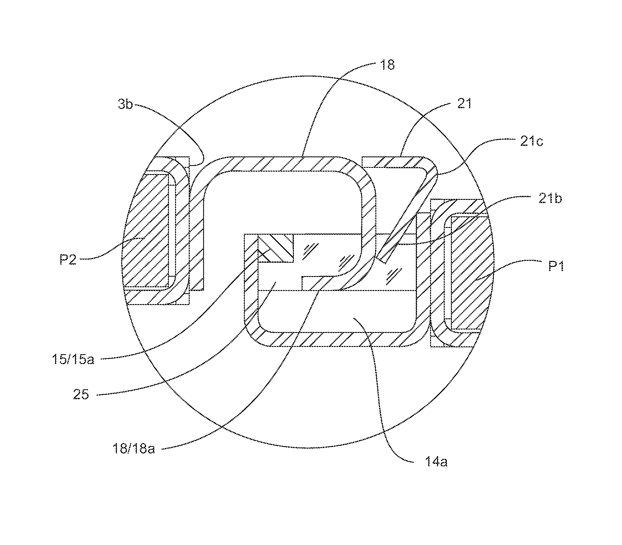
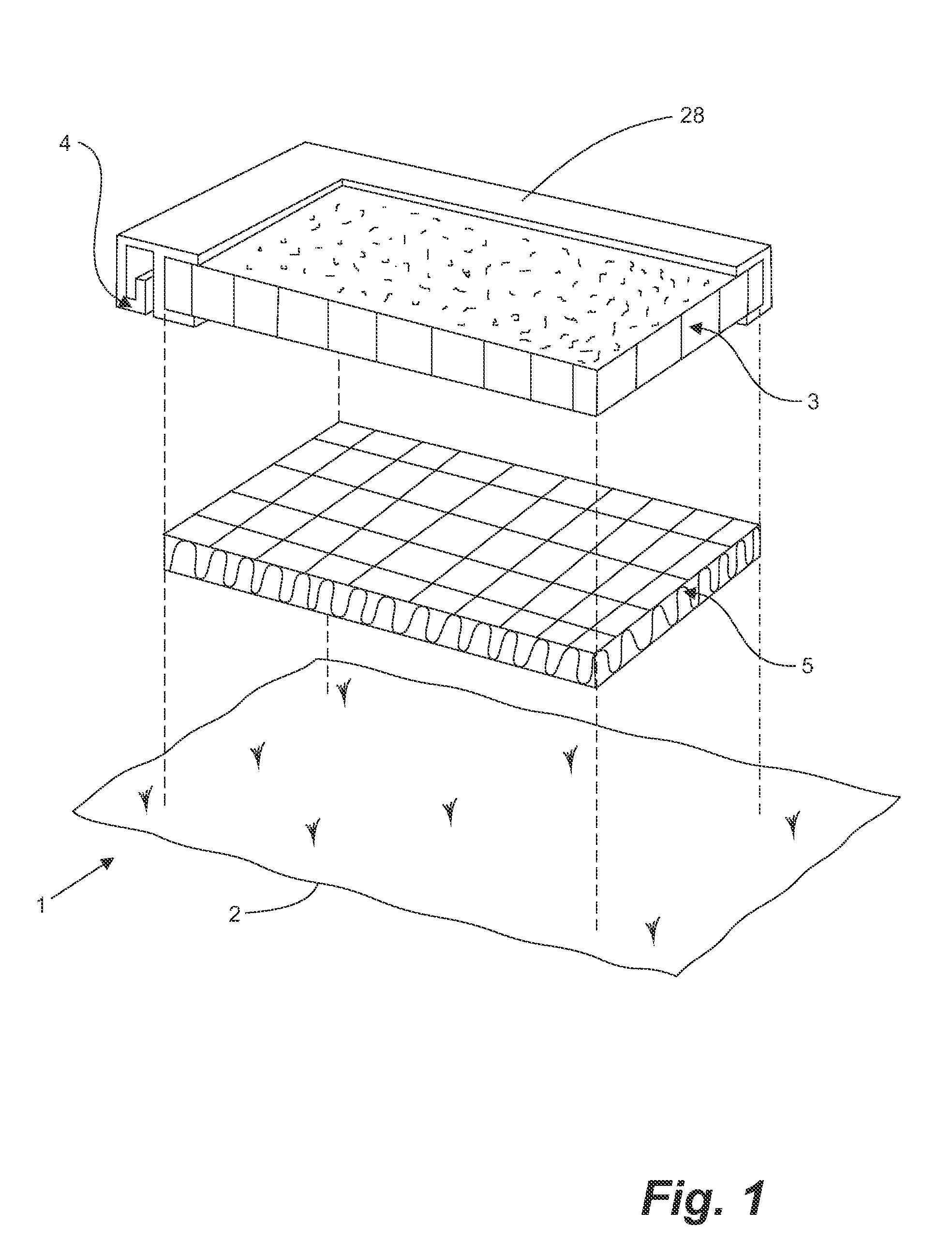
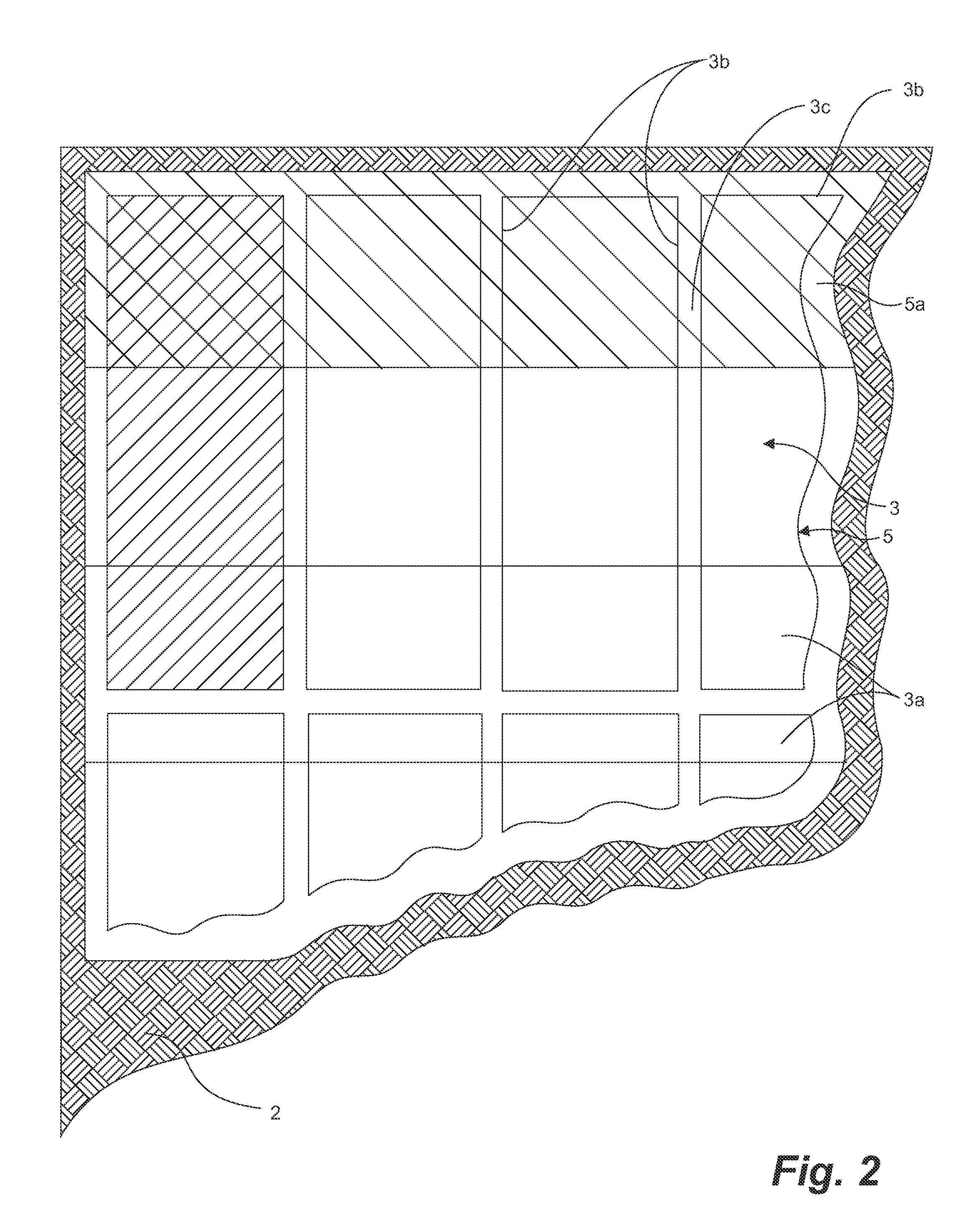
[0031]FIGS. 1 and 2 illustrate one embodiment of a rig mat system 1 for use over a terrain 2. Typical terrain sensitive to seepage include a frozen terrain or a swampy terrain. The assembled rig mat system 1 comprises a rig mat 3 formed by interconnecting a plurality of panels 3a. Each panel 3a comprises connecting edges 3b. The rig mat 3 is formed by interconnecting the plurality of panels 3a by their connecting edges 3b in an edge-to-edge arrangement by connection means 4. Interconnection of the panels 3a results in discontinuities 3c at the connecting edges 3b (best seen in FIG. 2). The discontinuities 3c in the rig mat 3 form a leak path from the rig mat 3...


PUM

PropertyMeasurementUnit
thickaaaaaaaaaa
thickaaaaaaaaaa
surface areaaaaaaaaaaa

Abstract

A multi-layer rig mat system and a method for implementing the rig mat system is provided. The rig mat system has a rig mat formed by interconnecting a plurality of panels in an edge-to-edge arrangement and one or more barrier layers placed between the rig mat and the terrain. The barrier layer prevents contamination of the terrain below the rig mat by water and other undesirable fluids seeping through gaps or discontinuities in the rig mat. The barrier layer also prevents heat transmission from the rig mat to the terrain below the rig mat.

Description

FIELD OF THE INVENTION[0001]The invention relates to a rig mat system placed over sensitive ground or terrain and methods for making same. More particularly, the rig mat has a plurality of interconnected panels to form a rigid working layer and one or more barrier layers are placed between the rig mat and the terrain.BACKGROUND OF THE INVENTION[0002]Rig mats, which are also known as rig pads and road mats, have been used, for example, for construction roadways, camp mats, and drilling rig platforms on surfaces such as Arctic tundra, in order to provide a temporary rigid surface on which equipment such as motor vehicles can operate. Rig mats may assist in reducing damage to the softer surface below, and may prevent motor vehicles or other objects from becoming bogged down. They can also prevent the softer surface from thawing when the ambient air temperatures are above freezing, thereby retaining the integrity of the rigid surface for supporting loads placed thereon. The service of r...

Claims


Application Information

Patent Timeline
Patent Type & Authority Patents(United States)
IPC IPC(8): E01C5/00
CPCE01C5/001E01C9/086E01C11/24E21B41/00E01C2201/12
Inventor BLEILE, LEONARDBATHELT, JARED MICHAELSTASIEWICH, BRIAN MATTHEW
Owner STRAD ENERGY SERVICES
Learn More