Torch for arc welding gun

a technology for arc welding and torch, which is applied in the direction of manufacturing tools, non-shielding electrode holders, electrode supporting devices, etc., can solve the problems of affecting the operability of the torch during welding operation, adversely affecting the operation of the torch, and the forward end of the torch is subject to substantial deterioration, so as to reduce the exposure to high temperatures and prevent spatter abrasion

Inactive Publication Date: 2013-10-08
LINCOLN GLOBAL INC
View PDF28 Cites 26 Cited by
  • Summary
  • Abstract
  • Description
  • Claims
  • Application Information

AI Technical Summary

Benefits of technology

[0011]The primary object of the present invention is to provide an improved welding torch for mounting on the front end of a welding gun, which torch has structure to protect the front end of the gun from heat deterioration and spatter erosion.
[0012]Yet another object of the invention is the provision of a welding torch, as defined above, which welding torch has a protective sleeve to insulate the end of the torch from heat and protect the diffuser orifices from abrasion by spatter.
[0013]Another object of the present invention is the provision of a contact tip for a welding torch, which contact tip has an intermediate flange used to hold a surrounding insulated protective sleeve onto the end of the main cylindrical assembly of the torch.
[0014]Still a further object of the present invention is the provision of a protective sleeve surrounding the end of the main cylindrical assembly of the torch and also the diffuser orifices of the torch to reduce exposure to high temperatures and prevent spatter abrasion.
[0015]Still another object of the present invention is the provision of a novel outer nozzle for a welding torch, which nozzle has a rear gripping mechanism comprising a rotatable actuator ring having an eccentric inner surface rotatable to clamp the rear end of the nozzle onto the outer surface of the torch.

Problems solved by technology

All of these requirements of a welding torch require complex machined components which substantially increases the cost of the torch and adversely affects the operability of the torch during the welding operation.
Furthermore, the welding operation itself creates spatter, especially during short circuit conditions, so the forward end of the torch is subject to substantial deterioration over time caused by spatter together with the tremendous arc temperature involved in the welding operation.
All of these adverse conditions create restraints in the design of a torch.
The design of the cooling jacket on the torch in existing torches has often proved unsatisfactory.
The more the torch is allowed to become elevated in temperature, the more troublesome the cooling problem for the torch.
This insulation material rapidly deteriorates if overheated.
Such closeness drastically increases the tendency for spatter to affect the laminar flow of shielding gas from the diffuser orifices.

Method used


Image

  • Torch for arc welding gun
  • Torch for arc welding gun
  • Torch for arc welding gun

Examples


Embodiment Construction

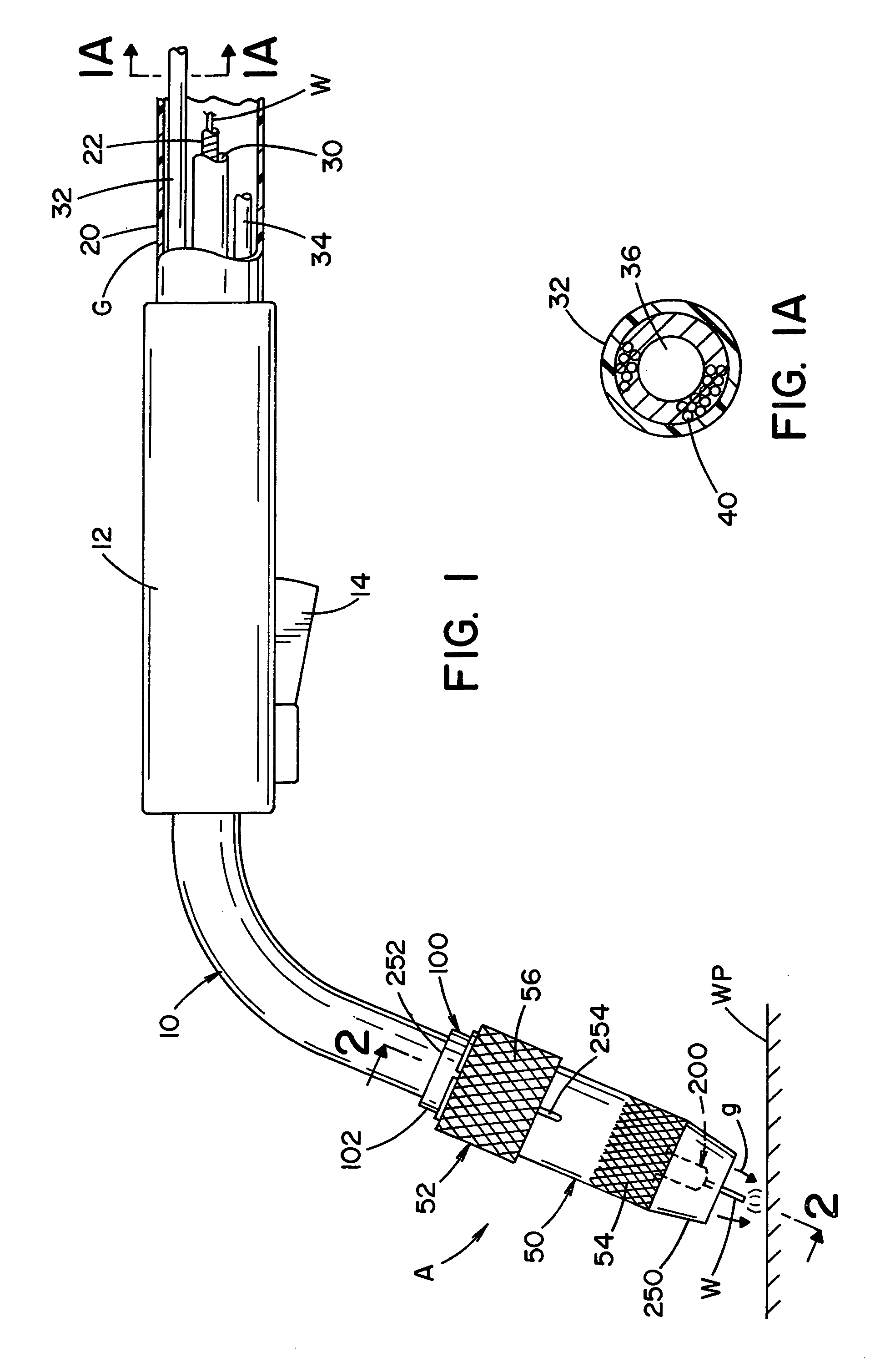
[0032]Referring now to FIGS. 1-7, the preferred embodiment of the present invention is illustrated as torch A, goose neck 10 extending from handle 12. An optional manually operated trigger 14 is illustrated for handle 12; however, in most embodiments, torch A is used in a robotic environment having no external trigger 14. The torch is at the front end of welding gun G, which gun is an elongated device extending from a wire feeder to the welding operation where wire W is melted and transferred to workpiece WP. The rear end of gun G, not shown, forms no part of the present invention except to realize that the gun includes a flexible tube 40 extending from rear wire feeder to handle 12 supporting torch A. Wire W of a given diameter is directed from the wire feeder to torch A through liner 22. Flexible, long tube 20 houses an inlet coolant conduit 32 and an outlet conduit 34 for directing coolant, such as water, into and away from torch A when the torch is a water cooled type torch as i...


PUM

PropertyMeasurementUnit
diameteraaaaaaaaaa
thicknessaaaaaaaaaa
heat resistantaaaaaaaaaa

Abstract

A welding torch comprising: a main cylindrical conductive assembly with a front diffuser section having a plurality of circumferentially spaced shielding gas diffuser orifices for directing shielding gas radially outwardly from the assembly, a forwardly facing threaded bore extending through a cylindrical support nose and an elongated wire passageway coaxial with the threaded bore and opening at the rear end of the assembly. An insulated, cylindrical protective sleeve fitted around both the support nose and the diffuser orifices where the sleeve has a front clearance opening and circumferentially spaced openings communicated with the diffuser orifices and a contact tip having a central wire guide bore with a diameter only slightly larger than the diameter of the welding wire, a threaded rear body, a front extension passing through the front clearance opening and a radially extending flange between the rear body and the front extension to hold the protective sleeve around the nose when the body is screwed into the threaded bore of the main assembly.

Description

INCORPORATION BY REFERENCE[0001]The design of the torch at the welding end of a gun is the subject of many publications that describe the background of the present invention. Some of these publications are United Kingdom application 2285404; Canadian application 2106837; Canadian application 2139152; European application No. 0590728 A1; and U.S. Pat. 5,313,046. These prior art examples show a welding torch of the type to which the present invention is directed and are incorporated by reference herein as background information. They also describe some of the attributes required for a welding torch.BACKGROUND OF INVENTION[0002]In electric arc welding, a “gun” is a flexible, elongated element having a rear end connected to a wire feeder and power source and a front end for a welding torch. The gun includes an elongated flexible conduit directing current and shielding gas from the wire feeder to the welding torch. A welding gun is employed for hand held welding and for robotic controlle...

Claims


Application Information

Patent Timeline
Patent Type & Authority Patents(United States)
IPC IPC(8): B23K9/173
CPCB23K9/123B23K9/173B23K9/282B23K9/285B23K9/295
Inventor ZAMUNER, FRANK
Owner LINCOLN GLOBAL INC
Why Eureka
Try Eureka