Scan driver and driving method thereof

a technology of driver and drive device, which is applied in the direction of digital storage, instruments, computing, etc., can solve the problems of increasing the size of the display panel of the display device, and achieve the reduction of the number of elements and signals used, simplified circuit configuration, and reduced layout area

Active Publication Date: 2013-10-08
SAMSUNG DISPLAY CO LTD
View PDF12 Cites 10 Cited by
  • Summary
  • Abstract
  • Description
  • Claims
  • Application Information

AI Technical Summary

Benefits of technology

[0042]Also, when comparing with a typical circuit configuration of a scan driver, the number of elements and signals that are used may be reduced such that the circuit configuration may be simplified and the layout area may be reduced. Accordingly, a probability of product deterioration may be reduced such that a yield may be improved.

Problems solved by technology

However, as the size of the display panel of the display device is increased and the driving method becomes complicated, the display device concurrently (e.g., simultaneously) applies a voltage (e.g., a predetermined voltage) to the plurality of scan lines such that all pixels may be concurrently (e.g., simultaneously) initialized or concurrently (e.g., simultaneously) light-emitted or stopped from light emitting, as well as have sequential data writing.

Method used


Image

  • Scan driver and driving method thereof
  • Scan driver and driving method thereof
  • Scan driver and driving method thereof

Examples


Embodiment Construction

[0050]In the following detailed description, only certain exemplary embodiments of the present invention have been shown and described, simply by way of illustration. As those skilled in the art would realize, the described embodiments may be modified in various different ways, all without departing from the spirit and scope of the present invention. Accordingly, the drawings and description are to be regarded as illustrative in nature and not restrictive. Like reference numerals designate like elements throughout the specification.

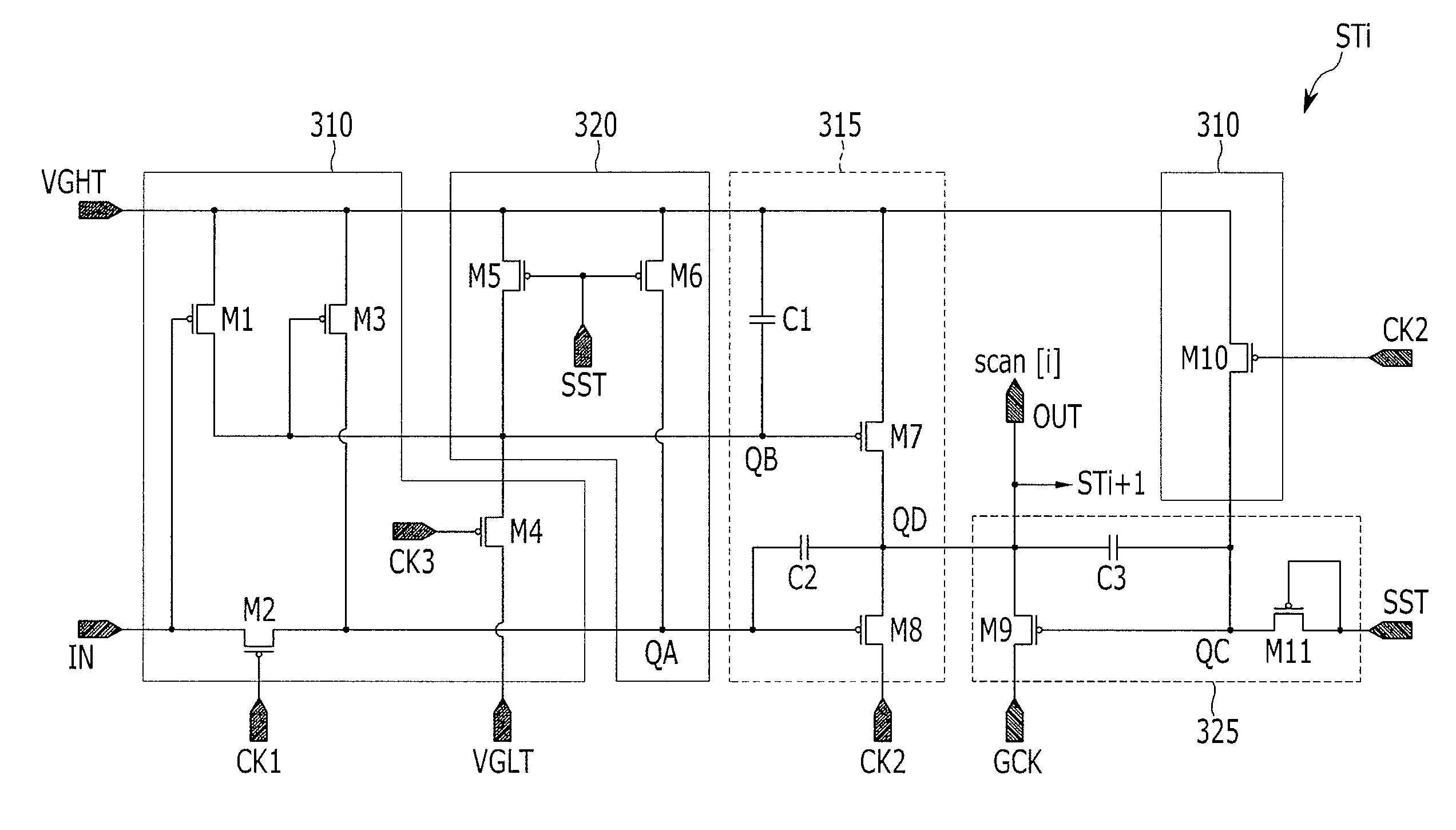
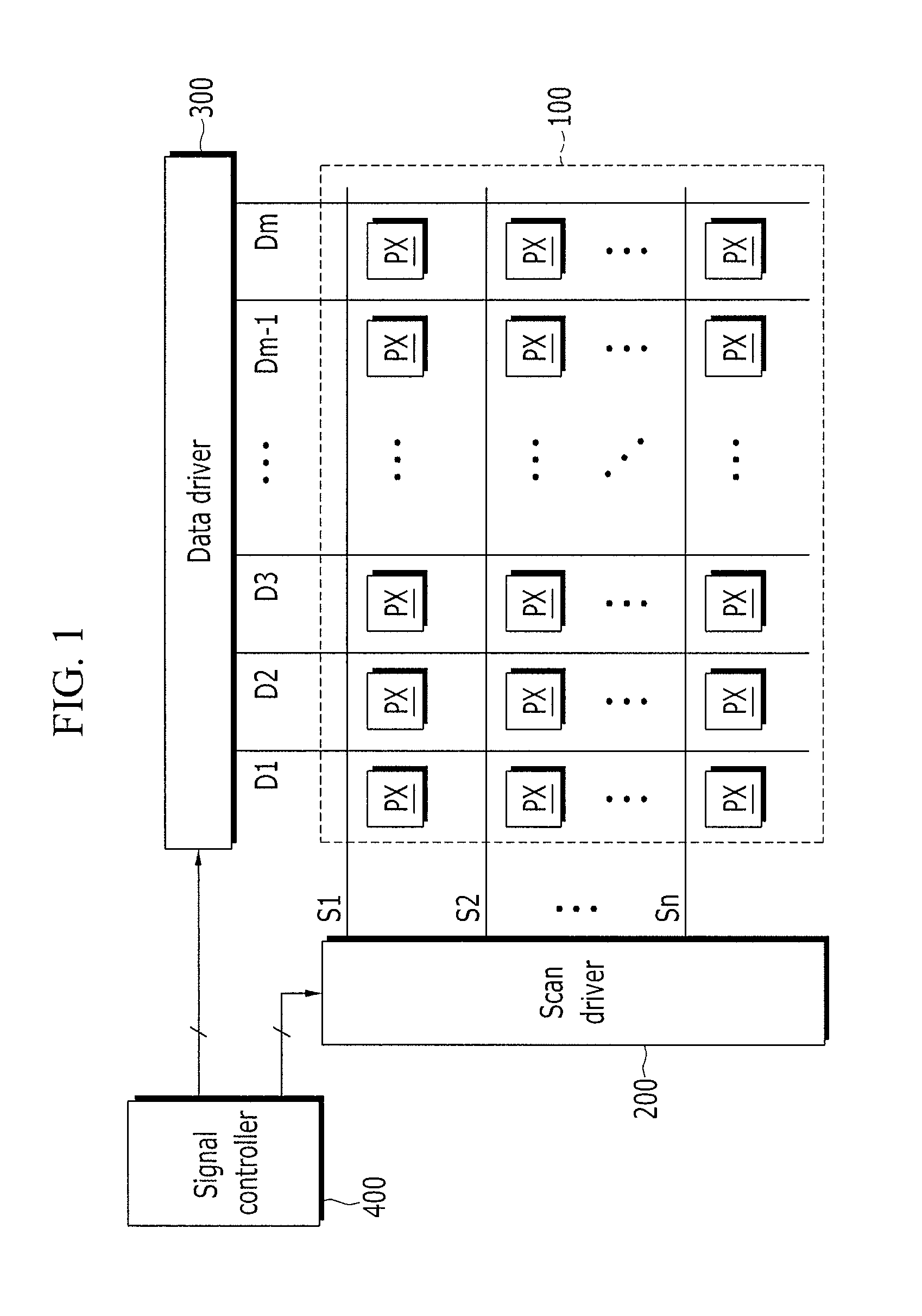
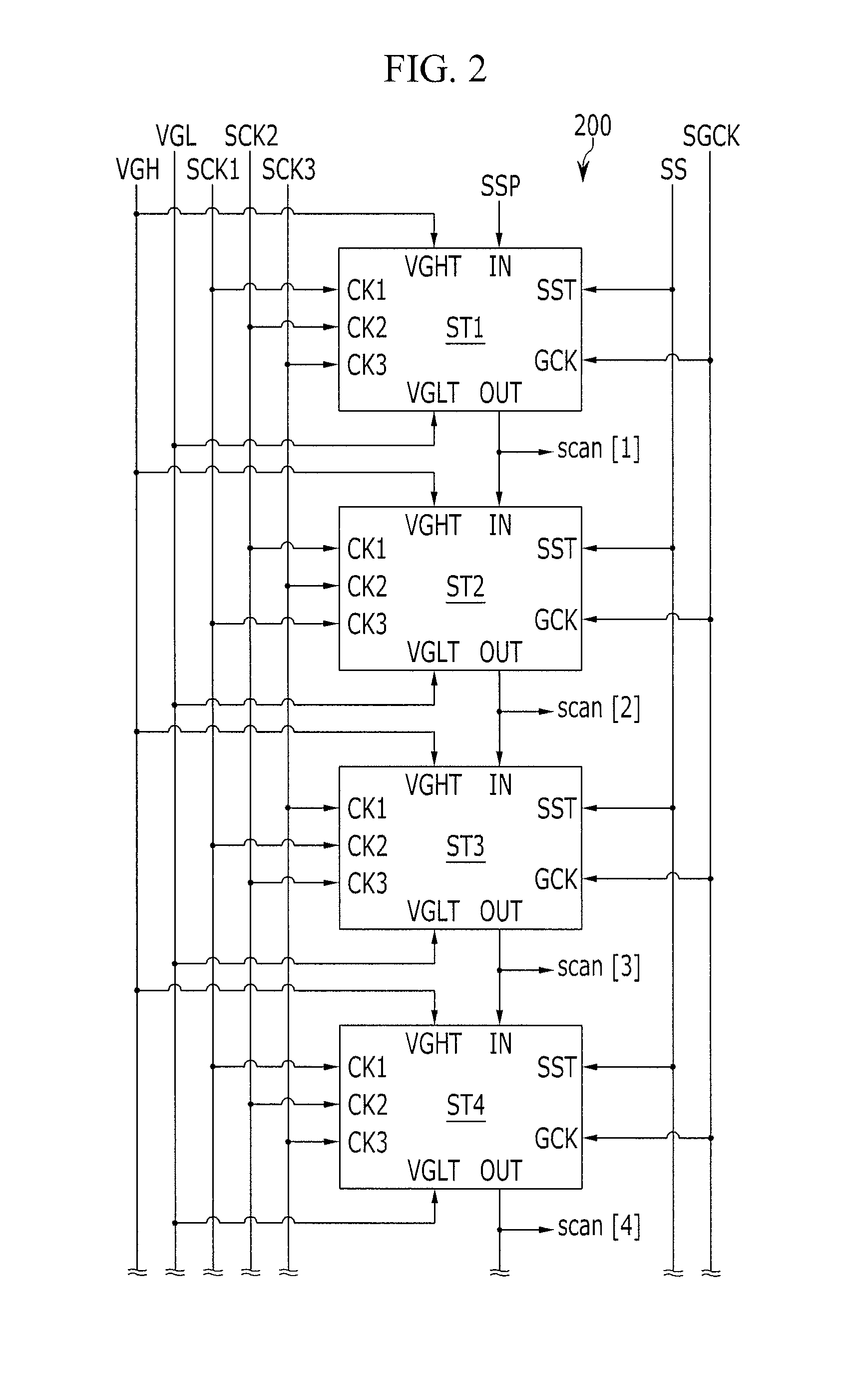
[0051]FIG. 1 is a block diagram of a display device according to an exemplary embodiment of the present invention, FIG. 2 and FIG. 8 are block diagrams of a scan driver according to exemplary embodiments of the present invention, and FIG. 3 is a circuit diagram of one stage of the scan driver shown in FIG. 2.

[0052]Referring to FIG. 1, a display device includes a display unit 100, a scan driver 200, a data driver 300, and a signal controller 400 for contro...


PUM


Abstract

A display device includes a plurality of scan lines and a scan driver. The scan driver includes a plurality of stages for transmitting a scan signal having a first voltage to the plurality of scan lines, and each of the stages includes a sequential switching unit, a sequential output unit, a concurrent switching unit, and a concurrent output unit. The concurrent output unit includes a first transistor for transmitting a second control signal to the output terminal according to a first control signal during a concurrent driving period before the scan signal is converted from a first level to a second level according to the second control signal, and a gate voltage of the first transistor is controlled by a voltage that is different from the first voltage according to the first control signal.

Description

CROSS-REFERENCE TO RELATED APPLICATION[0001]This application claims priority to and the benefit of Korean Patent Application No. 10-2011-0004076, filed in the Korean Intellectual Property Office on Jan. 14, 2011, the entire contents of which are incorporated herein by reference.BACKGROUND[0002]1. Field[0003]The present invention relates to a scan driver and a driving method thereof. More particularly, the present invention relates to a scan driver of a display device.[0004]2. Description of the Related Art[0005]An active display device, such as an organic light emitting diode (OLED) display and a liquid crystal display (LCD), includes a plurality of pixels disposed in a matrix format, defined by a plurality of scan lines extending in a row direction and a plurality of data lines extending in a column direction. A scan driver sequentially applies scan pulses to the plurality of scan lines, and a data driver transmits data signals to the plurality of data lines to write corresponding ...

Claims


Application Information

Patent Timeline
Patent Type & Authority Patents(United States)
IPC IPC(8): G06F3/038G09G5/00
CPCG09G3/3266G09G3/3674G11C19/184G11C19/28G09G2310/0205G09G2310/0267G09G3/20G09G3/30G09G3/36G09G2310/0286
Inventor PARK, SEONG-IL
Owner SAMSUNG DISPLAY CO LTD
Why Eureka
Try Eureka