Cooler arrangement for a drive train in a motor vehicle

a technology for cooling arrangement and drive train, which is applied in the direction of engine-driven generators, machines/engines, mechanical equipment, etc., and can solve problems such as reducing the efficiency of the drivetrain

Active Publication Date: 2013-10-15
MAHLE INT GMBH
View PDF33 Cites 18 Cited by
  • Summary
  • Abstract
  • Description
  • Claims
  • Application Information

AI Technical Summary

Benefits of technology

[0005]This may advantageously take place if the internal combustion engine is first set in operation at a relatively late time, that is to say if the cold motor vehicle initially starts with drive provided by the electric motor. In this case, the internal combustion engine may be pre-heated by means of the waste heat of the electric motor and of the associated auxiliary units, as a result of which the friction losses are reduced and better emissions values are also obtained. In a further operating state of the internal combustion engine, it is also conceivable to heat the transmission of the drivetrain, which transmission likewise generates relatively high friction losses, which reduce the efficiency of the drivetrain, in the cold state. The transmission is conventionally assigned to the relatively cool coolant circuit, and thus acts as a heat source in said circuit. By means of the connection, however, it is possible for the relatively high temperature level of the coolant circuit assigned to the internal combustion engine to be utilized for pre-heating the transmission. This is conceivable in particular if the motor vehicle is initially and / or predominantly operated using the internal combustion engine, that is to say if said internal combustion engine reaches its optimum operating temperature more quickly than the transmission, such that a transfer of heat via the connection to the transmission is expediently possible.
[0006]One preferred exemplary embodiment of the cooler arrangement is characterized in that the cooler arrangement has a valve arrangement which controls the connection. The two coolant circuits may be coupled to one another by means of the connection and the valve arrangement so as to enable an exchange of coolant and therefore of heat. The valve arrangement can control the correspondingly required coolant flows for this purpose, that is to say shut off or enable or control and / or throttle said flows. It is therefore possible, when the internal combustion engine is cold and at a standstill, for coolant to be conducted from the coolant circuit with the relatively low temperature level, for example from the second coolant circuit, through the cold internal combustion engine which therefore acts as a heat sink. The engine is heated without running, such that when the internal combustion engine is actually started, the friction and therefore fuel consumption have already been reduced. The heat generated in the second coolant circuit is thus retained within the overall cooling system and is not dissipated to the environment. When the coolant temperature at the outlet of the internal combustion engine is higher than the temperature upstream of a transmission oil cooler of the second coolant circuit, the valve arrangement may advantageously be switched such that heated coolant from the internal combustion engine can be supplied via the connection to the transmission oil cooler of the second coolant circuit. The friction in the transmission can thereby advantageously be reduced more quickly.
[0012]A further preferred exemplary embodiment of the cooler arrangement is characterized in that the valve arrangement has a second regulating valve which controls the second connecting line. The second connecting line can be blocked, opened or partially opened by means of the second regulating valve. It is consequently possible by means of the second regulating valve to control or regulate the exchange of heat or the exchange of coolant between the coolant circuits. This may advantageously take place as a function of the operating state of the motor vehicle, in particular as a function of the respective temperature level in the internal combustion engine and in the unit assembly. Closing the regulating valve consequently brings the coolant flow in the second connecting line to a standstill. Since the first and second coolant circuits are in each case closed systems, it is also possible by closing the second regulating valve to substantially prevent an overflow of coolant via the first connecting line, which preferably does not have a regulating valve.
[0013]A further preferred exemplary embodiment of the cooler arrangement is characterized in that the connection has a third connecting line which is connected between the first and second coolant circuits downstream of the internal combustion engine, downstream of the power electronics and upstream of the transmission. It is thus advantageously possible, via the third connecting line, for in particular hot coolant to be supplied, proceeding from the internal combustion engine, to the transmission oil cooler via a partial section of the second coolant circuit. It is advantageous that the power electronics can be bypassed by means of the third connecting line. It is thereby possible to prevent the power electronics from being heated above their admissible operating temperature for example in the event of hot coolant being transported proceeding from the internal combustion engine.

Problems solved by technology

In a further operating state of the internal combustion engine, it is also conceivable to heat the transmission of the drivetrain, which transmission likewise generates relatively high friction losses, which reduce the efficiency of the drivetrain, in the cold state.

Method used


Image

  • Cooler arrangement for a drive train in a motor vehicle
  • Cooler arrangement for a drive train in a motor vehicle

Examples


Embodiment Construction

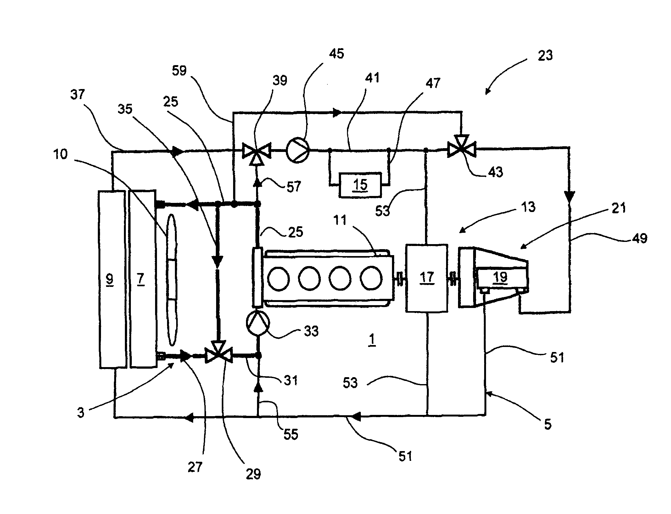
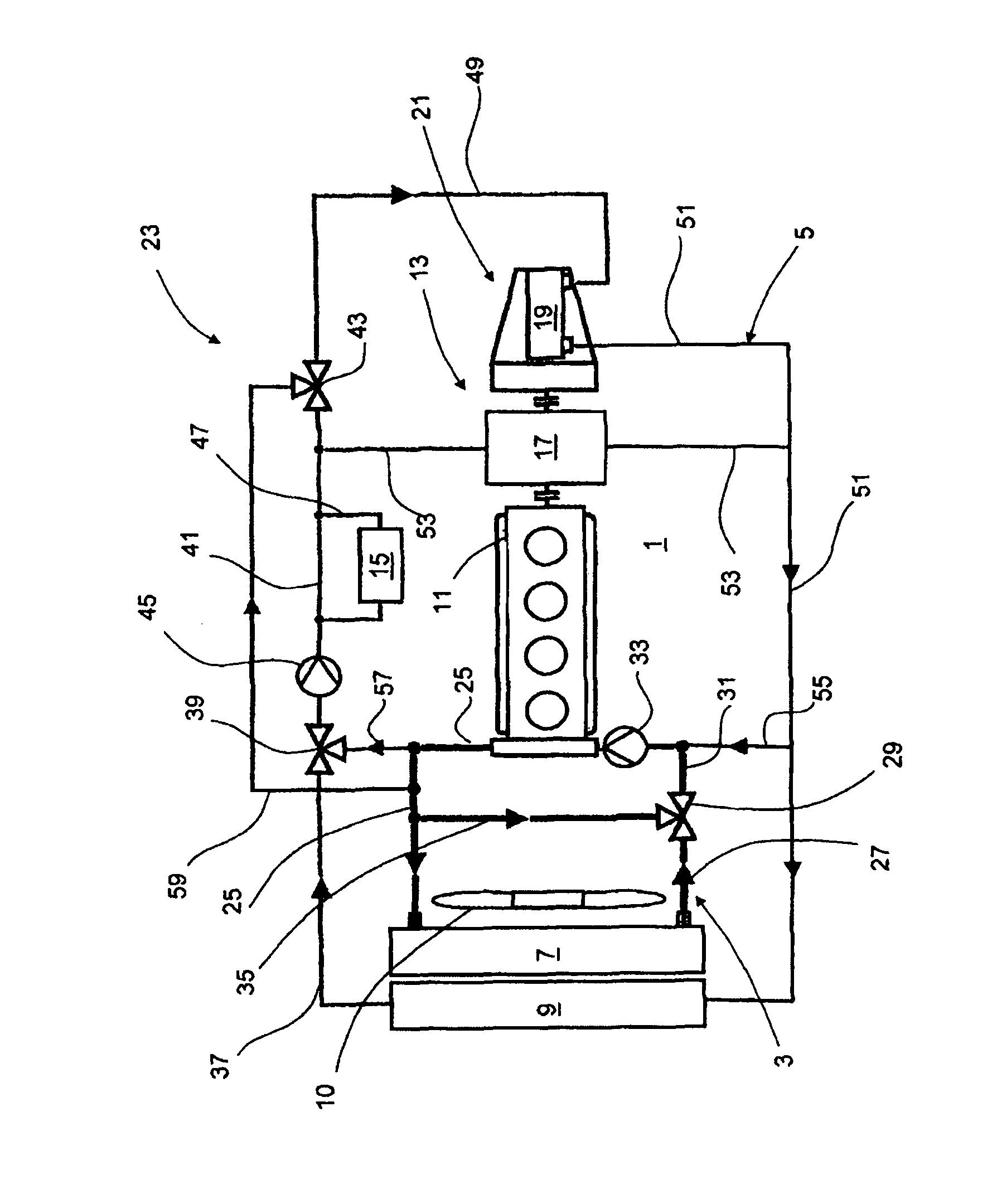
[0025]FIG. 1 shows a cooler arrangement 1 having a first coolant circuit 3 and a second coolant circuit 5. The first coolant circuit 3 has a first coolant cooler 7. The second coolant circuit 5 has a second coolant cooler 9. For the aeration of the coolant coolers 7 and 9, the cooler arrangement 1 may have a fan 10, for example a fan which is preferably controlled in a temperature-dependent fashion and which is driven electrically and / or coupled, in particular in a temperature-dependent fashion, to an internal combustion engine 11.

[0026]The first coolant circuit 3 is assigned to the internal combustion engine 11. The second coolant circuit 5 is assigned to a unit arrangement 13. The unit arrangement 13 has power electronics 15, an electric motor 17 and a transmission 19 which, together with the internal combustion engine 11, may be parts of a drivetrain 21 of a motor vehicle 23. The motor vehicle 23 may be a vehicle with hybrid drive, with the internal combustion engine 11 together ...


PUM


Abstract

The invention relates to a cooler arrangement for a drive train (21) in a motor vehicle (23). Said cooler arrangement comprises a first coolant circuit (3) with a first coolant cooler (7) as well as a second coolant circuit (5) with a second coolant cooler (9). The invention is characterized in that there is a connection between the first coolant circuit (3) and the second coolant circuit (5).

Description

BACKGROUND OF THE INVENTION[0001]The invention relates to a cooler arrangement for a drivetrain of a motor vehicle, having a first coolant circuit with a first coolant cooler, and having a second coolant circuit with a second coolant cooler.[0002]Cooler arrangements for a drivetrain of a motor vehicle are known. Such cooler arrangements are used in particular for motor vehicles with various units whose operating temperatures differ. In hybrid vehicles, it is for example possible for the internal combustion engine and the electric motor to be assigned in each case to one of the coolant circuits.[0003]It is an object of the invention to optimize the cooling of the drivetrain of a motor vehicle.SUMMARY OF THE INVENTION[0004]The object is achieved in a cooler arrangement for a drivetrain of a motor vehicle, having a first coolant circuit with a first coolant cooler, and having a second coolant circuit with a second coolant cooler, in that a connection is provided between the first coola...

Claims


Application Information

Patent Timeline
Patent Type & Authority Patents(United States)
IPC IPC(8): F02F1/14F01P1/06F01P5/10F01P7/00F01P7/02F01P3/20B60L50/16
CPCF01P3/20F01P7/165F01P2050/24F01P2050/30F01P2060/045
Inventor FELDHAUS, GEORGPANTOW, EBERHARD
Owner MAHLE INT GMBH
Why Eureka
Try Eureka