Wireless operating room communication system including video output device and video display

a technology of operating room communication and video display, which is applied in the field of wireless operating room communication system, can solve the problems of reducing the number of cables provided throughout the operating room, affecting the work area of surgeons or other medical personnel, and limiting the movement of surgical devices, including video displays, within the operating room

Active Publication Date: 2013-10-15
STRYKER CORP
View PDF10 Cites 23 Cited by
  • Summary
  • Abstract
  • Description
  • Claims
  • Application Information

AI Technical Summary

Benefits of technology

[0011]Further, the invention provides a video camera or other video device in an operating room having a wireless video connection with portable battery powered video displays provided therein. Such arrangements allow a user to freely move the video displays throughout the entirety of an operating room during a surgical procedure.

Problems solved by technology

The cables interfere with work areas of a surgeon or other medical personnel.
Further, the cables limit the movement of surgical devices, including video displays, within the operating room.
A bus arrangement, however, merely reduces the number of cables provided throughout an operating room and thus does not completely address the issues caused by the presence of cabling.
One reason wholly wireless operating room systems are not currently in use, is the inability to provide communication signals and video signals together on a broadcast channel due to potential errors in transmission of the signals caused by electromagnetic interference, along with a lack of bandwidth (high data rate) due to the typically large bandwidth (high data rate) required for video signals.
Audio signals, such as voice commands transmitted from a wireless microphone, are provided with a lesser degree of priority and thus less accurate signal transmission than high priority control command signals.

Method used


Image

  • Wireless operating room communication system including video output device and video display
  • Wireless operating room communication system including video output device and video display
  • Wireless operating room communication system including video output device and video display

Examples


Embodiment Construction

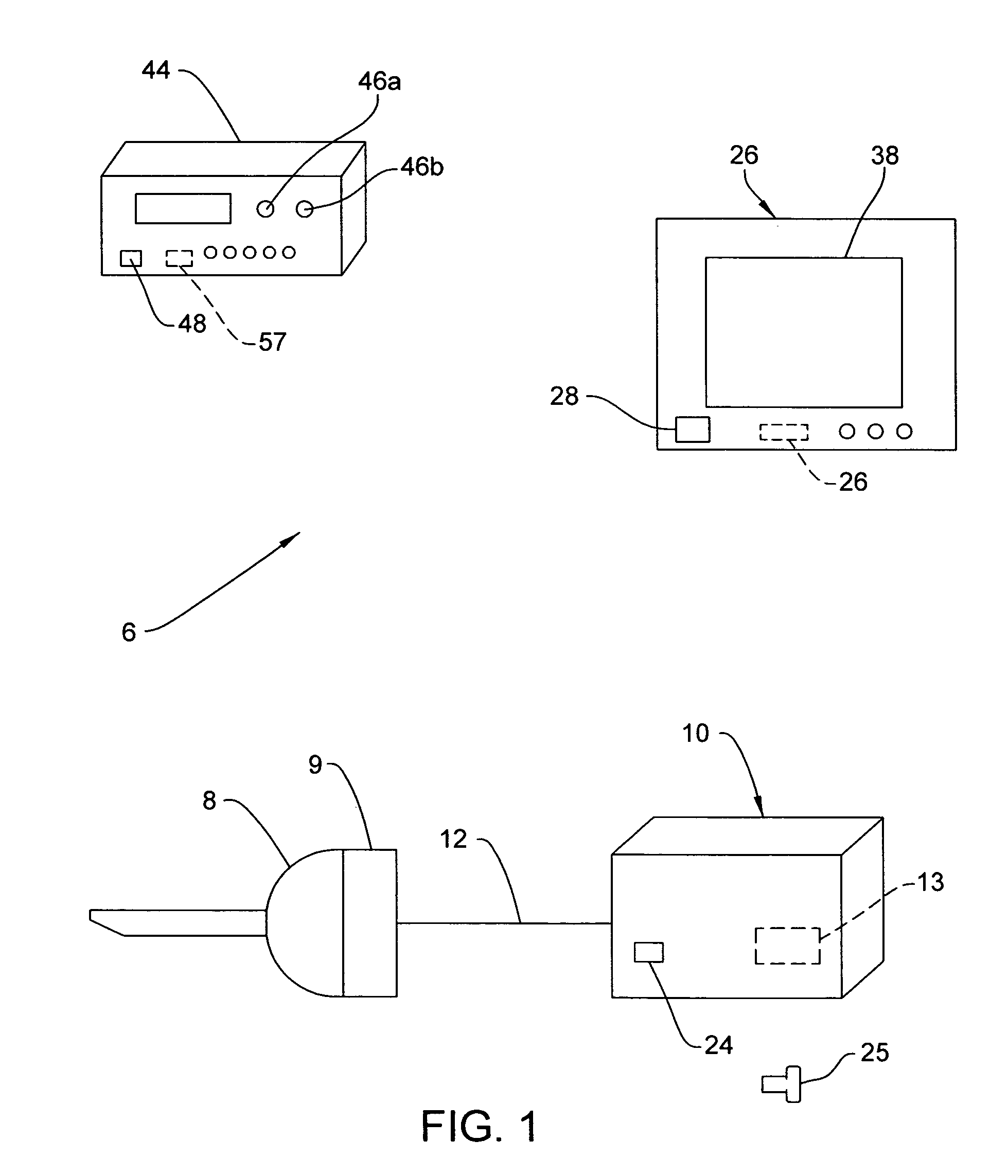
[0023]FIG. 1 shows a wireless operating room control system 6 including an endoscope 8, a camera head 9 and a wireless video transmitter unit 10 connected to the camera head 9 by a video cable 12.

[0024]As shown in FIG. 2, the wireless video transmitter unit 10 receives an image output from the camera head 9 carried on the video cable 12. A portable battery 13 provides power to the wireless video transmitter unit 10.

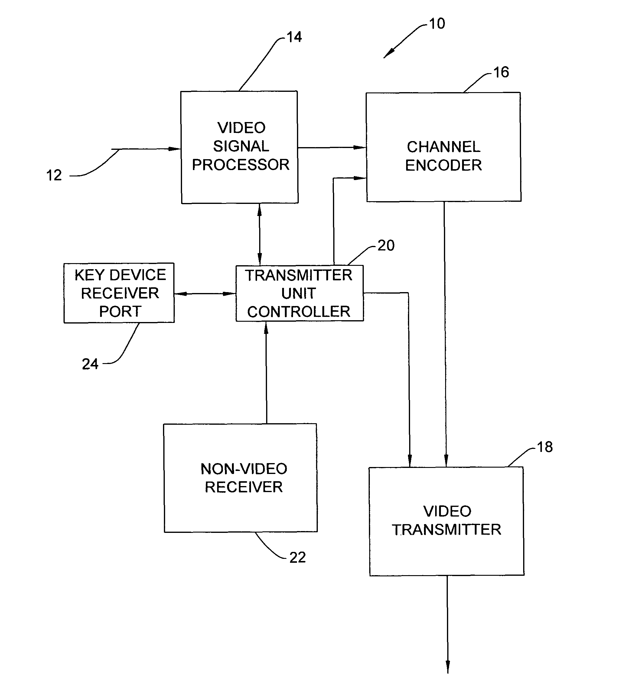
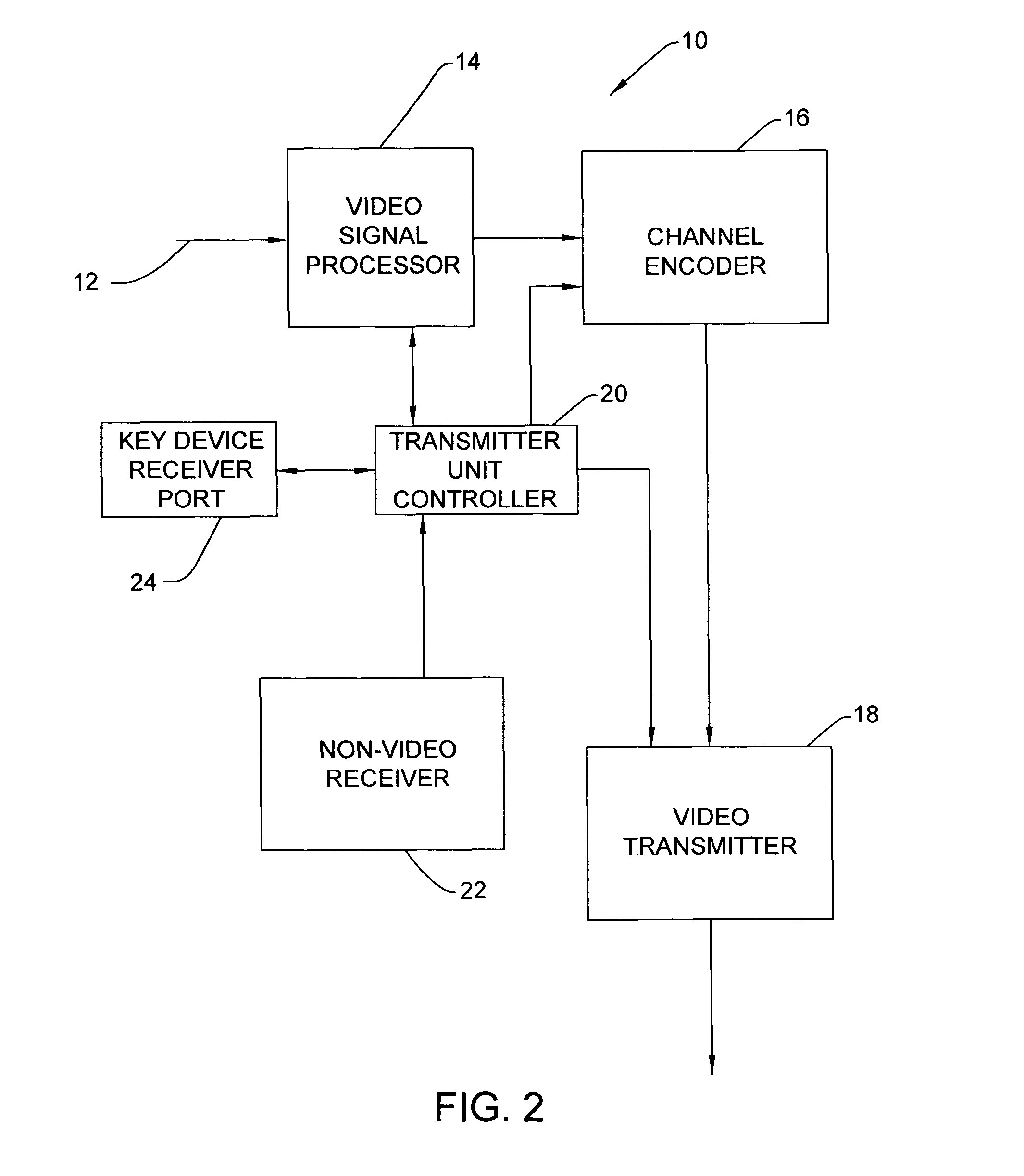
[0025]Signal processor 14 of the transmitter unit 10 processes the image signal and provides the output to a channel encoder 16. The channel encoder 16 provides an output to broadcast video transmitter 18. Transmitter unit controller 20 of the wireless video transmitter unit 10 connects to and communicates with the signal processor 14. The unit controller 20 also connects to the channel encoder 16, video transmitter 18 and a non-video transmitter unit receiver 22. Key device receiving port 24 connects to the controller 20. A key device 25 is provided for insertion into po...


PUM


Abstract

A wireless operating room communication system provides wireless transmission of video signals from a wireless camera or a wireless transmitter unit to a portable wireless display unit. A wireless multiple device control unit is in wireless communication with the transmitter unit, the display unit, and a plurality of surgical devices disposed within the operating room. Each of the surgical devices has a video receiver to obtain a video signal to synchronize the devices and units. The video transmitter unit has a video transmitter and the other units or devices have a non-video transmitter. The arrangement enables transmission of device control signals on the same channel as the video signal. In response to changes in bandwidth, the video transmitter unit reduces the video signal to enable transmission thereof to the video display unit, while maintaining robustness of the control signals.

Description

CROSS REFERENCE TO RELATED APPLICATION[0001]This application is the National Stage of International Application No. PCT / US2009 / 005934, filed Oct. 30, 2009, which claims the benefit of U.S. Provisional Application Ser. No. 61 / 199 921, filed Nov. 21, 2008, which is incorporated herein by reference in its entirety.FIELD OF THE INVENTION[0002]This invention is directed to a wireless operating room communication system that transmits data signals, audio signals and video signals among devices provided in an operating room.BACKGROUND OF THE INVENTION[0003]The remote control of application devices connected to each other through hard-wire connections is well known in an operating room. For instance, a controller having voice-activation and a touchscreen control device is capable of selectively controlling a plurality of surgical devices in an operating room. Such surgical devices include a hand-held powered cutting device with an irrigation device, an electrocautery device, a digital camer...

Claims


Application Information

Patent Timeline
Patent Type & Authority Patents(United States)
IPC IPC(8): A61B1/04A62B1/04A61B1/06
CPCA61B17/00A61B19/5225H04N5/232H04N5/23206A61B2017/00221A61B90/37A61B1/00016
Inventor NAMBAKAM, VASUDEVSHEN, JOHNTALBERT, JOSHUAMAHADIK, AMIT
Owner STRYKER CORP
Why Eureka
Try Eureka