Dual phase-locked loop circuit and method for controlling the same

a phase-locked loop and loop circuit technology, applied in the direction of phase difference detection angle demodulation, automatic control of pulses, electrical equipment, etc., can solve the problems of reducing the capability of restraining noise, failure to remove excessive noise, and both circuits still have their disadvantages, so as to reduce additional circuits, small loop bandwidth, and increase the tuning frequency range

Active Publication Date: 2013-10-22
MEDIATEK INC
View PDF12 Cites 6 Cited by
  • Summary
  • Abstract
  • Description
  • Claims
  • Application Information

AI Technical Summary

Benefits of technology

[0008]An object of the present invention is to provide a dual PLL circuit and a method for controlling the same, which are capable of enlarging a tuning frequency range while maintaining a small loop bandwidth, so as to reduce additional circuits, reduce design complexity of the dual PLL circuit and improve performance of the dual PLL circuit.
[0011]A dual PLL circuit and a method for controlling the same according to the present invention respectively comprise a coarse-tuning circuit and a coarse-tuning step, which are capable of enlarging a frequency tuning range while maintaining a small loop bandwidth, as well as reducing design complexity of the dual PLL circuit and improving performance of the dual PLL circuit. Further, the coarse-tuning circuit replaces a filter capacitor having large capacitance by a resistor having large resistance to obtain a large time constant and reduce capacitance of a loop filter, so as to prevent the usage of an off-chip capacitor and reduce product cost.

Problems solved by technology

According to a relationship that a gain of an oscillator is directly proportional to its loop bandwidth, a greater gain may result in a wider loop bandwidth of the PLL circuit, thus causing a failure in removing excessive noise and degrading the capability of restraining noise.
Although the foregoing two circuits overcome the dilemma between the wide frequency range and the narrow loop bandwidth to a certain extent, both of the circuits still have their disadvantages.
A disadvantage of the single-path PLL circuit is that product cost is increased for the reason that the filter capacitor has to be designed as an off-chip capacitor since it is too large to be integrated into an integrated circuit (IC).
A disadvantage of the PLL circuit with digital control is that it can not keep track of and adapt to variations of temperature or technique variables.

Method used


Image

  • Dual phase-locked loop circuit and method for controlling the same
  • Dual phase-locked loop circuit and method for controlling the same
  • Dual phase-locked loop circuit and method for controlling the same

Examples


first embodiment

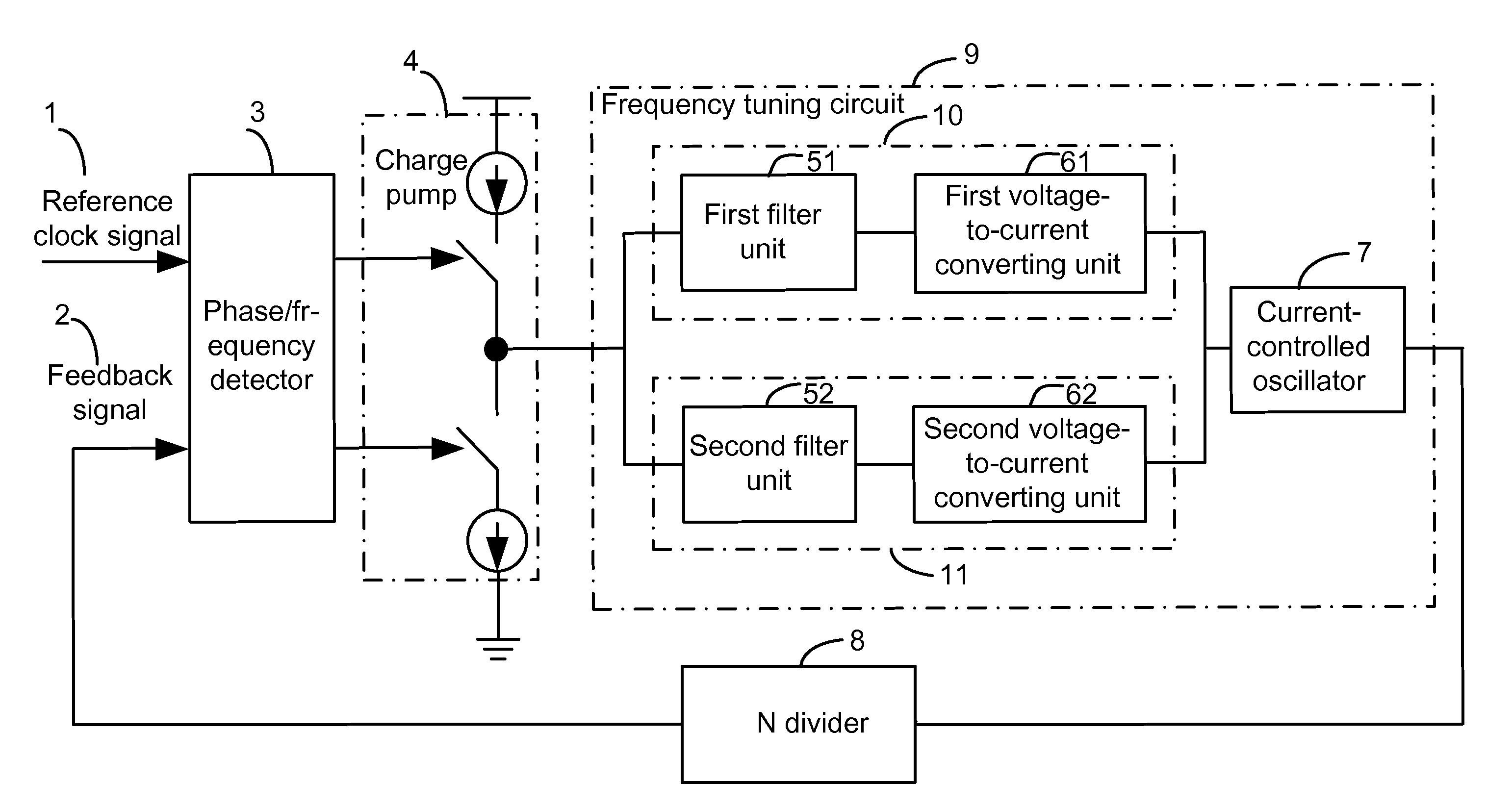
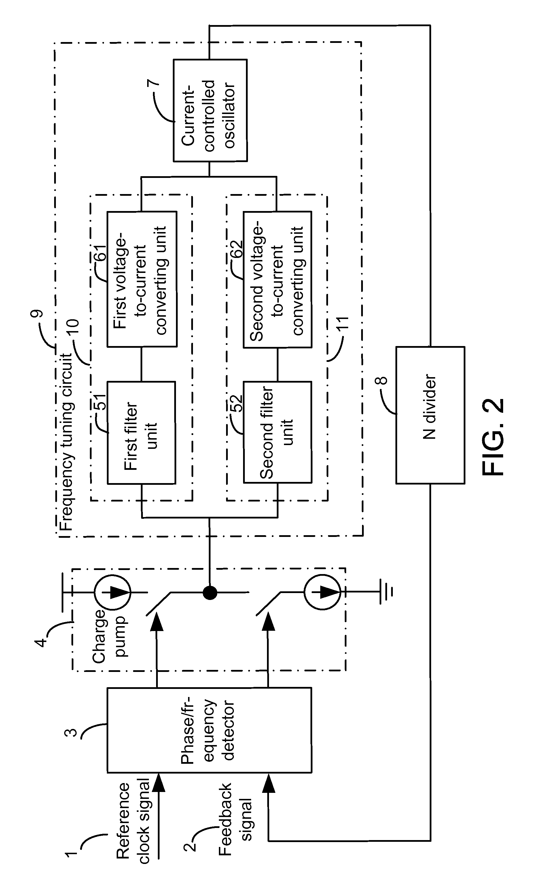
[0021]FIG. 2 shows a schematic diagram of a dual PLL circuit in accordance with the present invention. The dual PLL circuit according to the present invention is, e.g., a dual PLL circuit with a high frequency and a narrow bandwidth. In this embodiment, the dual PLL circuit comprises a phase / frequency detector 3, a charge pump 4, a frequency tuning circuit 9 and an N divider 8, which are coupled in sequence. A reference clock signal is inputted at one input end of the phase / frequency detector 3. An output signal generated at an output end of the frequency tuning circuit 9 is transmitted to the N divider 8 to generate a feedback signal to be fed into the other input end of the phase / frequency detector 3. The frequency tuning circuit 9 comprises a coarse-tuning circuit 10, a fine-tuning circuit 11, and a CCO 7. The coarse-tuning circuit 10 is connected in parallel to the fine-tuning circuit 11. The CCO 7 has its one end coupled to the coarse-tuning circuit 10 and the fine-tuning circu...

third embodiment

[0034]FIG. 6 is a schematic diagram of a dual PLL circuit in accordance with the present invention. In this embodiment, the dual PLL circuit comprises a phase / frequency detector 3, a charge pump 4, a frequency tuning circuit 9 and an N divider 8, which are coupled in sequence. A reference clock signal is inputted to one input end of the phase / frequency detector 3. An output signal generated at an output end of the frequency tuning circuit 9 is transmitted to the N divider 8 to generate a feedback signal to be fed into another input end of the phase / frequency detector 3.

[0035]In this embodiment, the frequency tuning circuit 9 of the dual PLL circuit comprises a filter unit 5 that is different from the first filter unit 51 and the second filter unit 52 described in the first embodiment. FIG. 7 shows a schematic diagram of the filter unit 5 in accordance with a third embodiment of the present invention. The filter unit 5 also comprises the first filter unit 51 and the second filter uni...


PUM


Abstract

A dual phase-locked loop (PLL) circuit includes a phase / frequency detector, a charge pump, a frequency tuning circuit and an N divider. The frequency tuning circuit includes a coarse-tuning circuit, for coarse-tuning an output frequency of the dual PLL circuit to approximate a target frequency; a fine-tuning circuit, for fine-tuning the output frequency of the dual PLL circuit to the target frequency; and a current control oscillator (CCO), for generating an output signal of the dual PLL circuit. The output frequency of the output signal is equal to the target frequency.

Description

CROSS REFERENCE TO RELATED PATENT APPLICATION[0001]This patent application is based on China, P.R.C. patent application No. 200910157826.8 filed on Jul. 7, 2009.FIELD OF THE INVENTION[0002]The present invention relates to a phase-locked loop (PLL) circuit, and more particularly, to a dual PLL circuit and a method for controlling the same.BACKGROUND OF THE INVENTION[0003]A frequency synthesizer composed of a PLL circuit is an important approach for generating clock signals. The frequency synthesizer inputs a low-frequency reference signal with high stability and high accuracy to output a series of high-frequency clock signals.[0004]FIG. 1 is a schematic diagram of a conventional PLL circuit. The operating principle of the conventional PLL circuit is described below. A phase / frequency detector 3 uses a reference clock signal as a reference to compare a frequency and a phase of the reference clock signal with those of a feedback signal outputted from an output end of an N divider 8. Wi...

Claims


Application Information

Patent Timeline
Patent Type & Authority Patents(United States)
IPC IPC(8): H03L7/06
CPCH03L7/093H03L7/0995H03L7/1075
Inventor LIU, YONG-WANGLU, WEN-CAISMITH, STERLING
Owner MEDIATEK INC
Why Eureka
Try Eureka