Sealing valve arrangement for a shaft furnace charging installation

a technology for sealing valves and furnaces, which is applied in the direction of furnaces, charge manipulation, lighting and heating apparatus, etc. it can solve the problems of requiring an additional second actuator, shutter-actuating devices, and limiting the maximum filling height of the hopper, so as to reduce the time-consuming installation and removal, and the effect of less prone to jamming

Inactive Publication Date: 2013-10-29
PAUL WURTH SA
View PDF7 Cites 16 Cited by
  • Summary
  • Abstract
  • Description
  • Claims
  • Application Information

AI Technical Summary

Benefits of technology

[0006]In view of the above, the invention provides a sealing valve arrangement with a dual-motion shutter-actuating device that is less prone to jamming and that allows for less time-consuming installation and removal.
[0013]By virtue of the coaxial arrangement of the hollow first tilting shaft and the reference rod, only one opening needs to be precisely machined in the fixed structure, e.g. the lower sealing valve housing or the hopper shell. Furthermore, thermally induced deformation of the structure on which the shutter-actuating device is supported can no longer cause jamming because all axes are maintained parallel and at proper distances by the device itself, independently of the supporting structure. Moreover, the shutter-actuating device can be handled as a single unit during installation and maintenance.
[0015]In a preferred embodiment of the mechanism that imparts rotation to the secondary tilting arm, this mechanism has a driving side in engagement with the second tilting shaft for imparting rotation to the secondary tilting arm about the second axis, with the secondary tilting arm being fixed in rotation onto the second tilting shaft. Preferably, the mechanism is enclosed in a casing supported on the primary arm. In this embodiment, the second tilting shaft is arranged to pass through a bore in the primary tilting arm or in the casing. This bore is equipped with a seal that seals the interior of the casing against the outside. The latter configuration reliably protects the rotating mechanism, which is typically exposed to a severe atmosphere.
[0016]In a simple an reliable embodiment of the mechanism, the second tilting shaft is configured as a crankshaft and the mechanism comprises a connecting rod connected at one end to the crankshaft for imparting rotation to the secondary tilting arm. At the other end, the connecting rod may for instance engage an eccentric pivot on the stationary reference member. It may also have a cam follower pin guided in a cam groove in the reference member. The cam groove preferably has a contour that the distance between the cam follower pin and the first axis during an initial phase of motion from the closed to the open position. The latter embodiment enables lifting the shutter in nearly axially from the valve seat during the initial phase of motion when opening and the final phase when closing. In this embodiment, the mechanism preferably has a linear guide maintaining the cam follower pin in engagement in the reference cam groove and guiding the second end portion of the connecting rod so as to constrain motion of the cam follower pin relative to the primary tilting arm to a linear motion.

Problems solved by technology

In other words, this valve arrangement requires a certain free height inside the sealing valve housing and limits the maximum filling height of the hoppers.
A drawback of these types of shutter-actuating devices however lies in that they require an additional second actuator when compared to flap-type valves.
Even though it enables dual-motion by means of a single actuator, major drawbacks of the arrangement according to EP 2000547 reside in susceptibility to misalignment and a cumbersome installation and removal procedure, e.g. for repair or replacement.
In fact, misalignment between the two groups of rotation axes on either side of the valve seat and in between the axes of each group can occur, e.g. due to asymmetrical thermal dilatation of the valve housing or due to improper machining.
Such misalignment could lead to premature wear, insufficient sealing contact between the shutter and the seat, and even to complete blockage or jamming of the shutter-actuating device.

Method used


Image

  • Sealing valve arrangement for a shaft furnace charging installation
  • Sealing valve arrangement for a shaft furnace charging installation
  • Sealing valve arrangement for a shaft furnace charging installation

Examples


Embodiment Construction

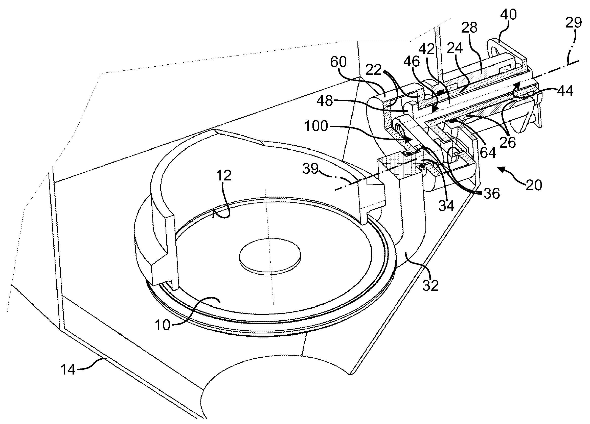
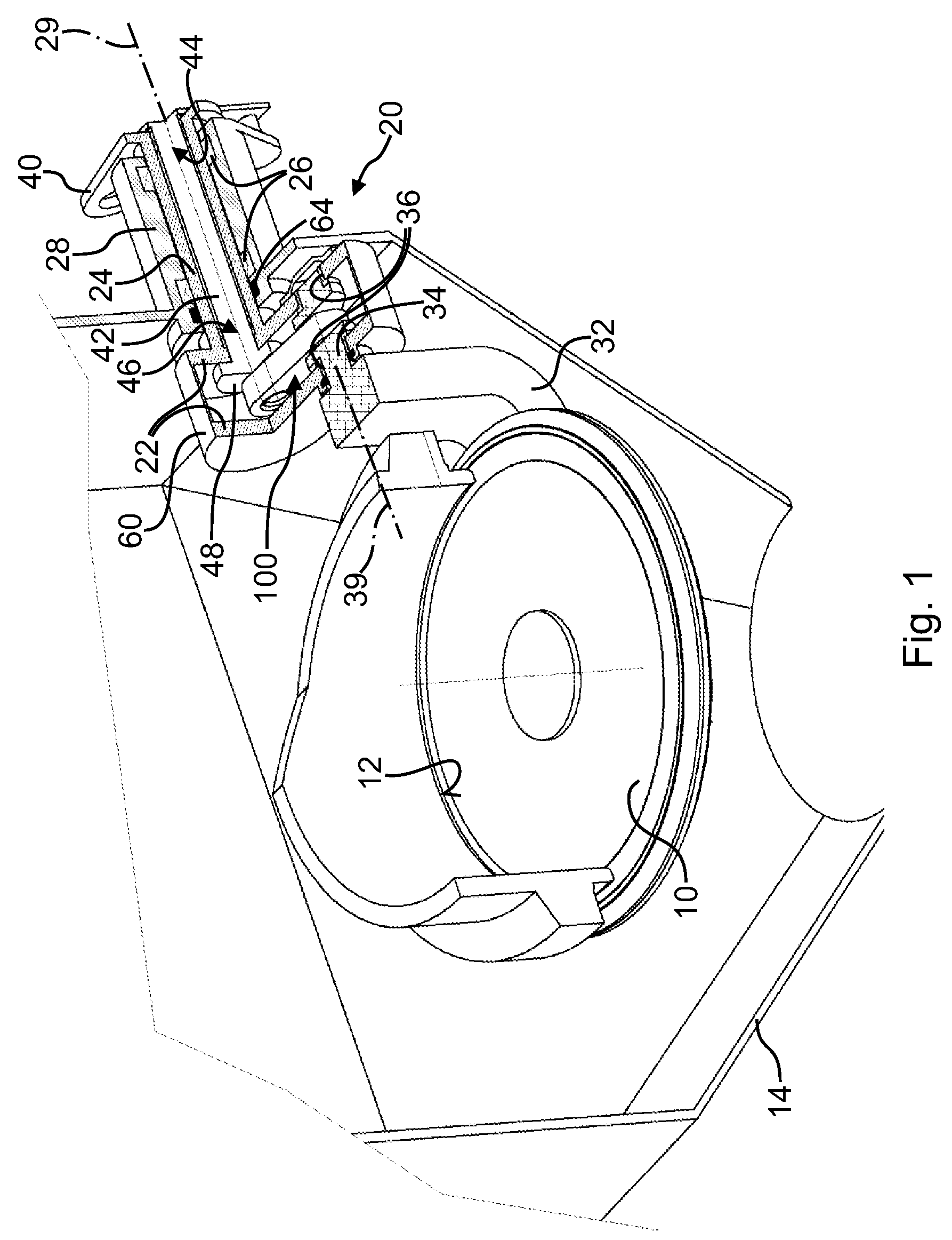
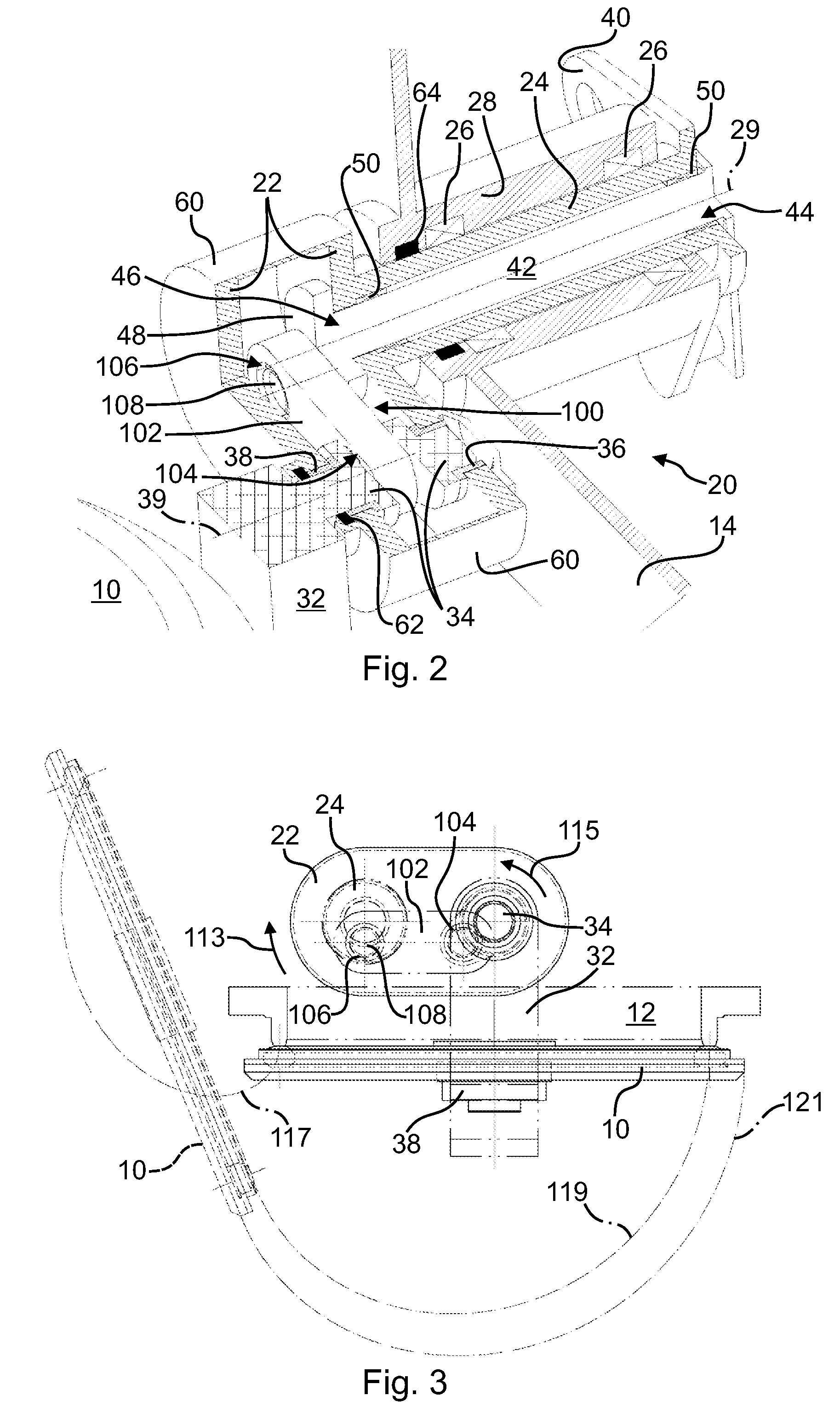
[0030]FIGS. 1-3 illustrate a first embodiment of sealing valve arrangement for a shaft furnace charging installation, in particular a blast furnace charging installation. The arrangement has a disc-shaped shutter 10 (closure member) that cooperates with a conical valve seat 12 for gas-tight closure. In this embodiment, the valve seat 12 is arranged on the lower end of a tubular channel that typically communicates, via a material gate valve, with the lower outlet of an intermediate storage hopper (not shown). Accordingly, in FIGS. 1-3, the valve seat 12 and the shutter 10 are arranged in a funnel shaped lower sealing valve housing 14 the outlet of which feeds material to a charge material distribution device. As will be understood, the presently proposed arrangement can equally be used as an upper sealing valve arrangement for sealing the inlet of an intermediate storage hopper (not shown). FIGS. 1-3 show the closed position, in which the shutter 10 is in sealing contact with the val...


PUM

PropertyMeasurementUnit
angleaaaaaaaaaa
angleaaaaaaaaaa
distanceaaaaaaaaaa

Abstract

A sealing valve arrangement for a shaft furnace charging installation includes a shutter-actuating device for moving a shutter between a closed position in sealing contact with a valve seat and an open position remote from the valve seat. The shutter-actuating device is of the dual-motion type and includes a primary tilting arm on a first tilting shaft defining the first axis and is equipped with bearings supporting the primary tilting arm. A secondary tilting arm carries the shutter is connected to a second tilting shaft that defines a second substantially parallel axis and has bearings that support the secondary tilting arm on the primary tilting arm. The shutter-actuating device has a mechanism configured to tilt the secondary tilting arm when the primary tilting arm is tilted.The first tilting shaft is configured as hollow sleeve shaft and the shutter-actuating device includes a reference rod extending through the first tilting shaft.

Description

TECHNICAL FIELD[0001]The present invention generally relates to a sealing valve arrangement for a shaft furnace charging installation and more specifically to an upper or lower sealing valve arrangement for preventing furnace gas loss in a blast furnace charging installation.BRIEF DESCRIPTION OF RELATED ART[0002]Shaft furnace charging installations of the BELL LESS TOP® type have found widespread use in industry during the last decades. An early example of such an installation is disclosed e.g. in U.S. Pat. No. 4,071,166. This installation minimizes escape of blast furnace gas from the furnace throat by operating one or more intermediate charge material storage hoppers in the manner of a sluice or airlock. To this effect, each hopper has an upper sealing valve and a lower sealing valve for sealing closure of the hopper inlet and outlet respectively. During filling of the hopper, the upper sealing valve is open whilst the lower sealing valve is closed. When material is charged from t...

Claims


Application Information

Patent Timeline
Patent Type & Authority Patents(United States)
IPC IPC(8): F16K31/44
CPCC21B7/18F27D99/0073F27D3/10F27B1/20
Inventor THILLEN, GUYLOUTSCH, JEANNOTHUTMACHER, PATRICKPARASCH, FREDERIC
Owner PAUL WURTH SA
Why Eureka
Try Eureka