Energy predictive buck converter

a buck converter and energy prediction technology, applied in the direction of power conversion systems, dc-dc conversion, instruments, etc., can solve the problems of gross misrepresentation of energy supply by the ramp, limited advantages of energy balancing in the buck converter, etc., to achieve energy balancing, maintain energy balance, and optimize transient response and stability

Active Publication Date: 2013-10-29
COGNIPOWER LLC
View PDF7 Cites 5 Cited by
  • Summary
  • Abstract
  • Description
  • Claims
  • Application Information

AI Technical Summary

Benefits of technology

[0006]Since energy demand is responsive to output error, which error remains uncorrected without energy balance, an energy demand signal tends to be self-preserving from cycle to cycle, even if partial error correction has occurred. In most converters, some sort of ramp more or less accurately represents energy supply. If this ramp be reset for each chopping cycle, whilst an inductor continues to charge from a given cycle to a later cycle, this ramp will grossly misrepresent energy supply. If, however, inductive current, or a volt-time representation thereof, is incorporated into the energy supply term, energy supply information survives from cycle to cycle allowing inductive energy supply to be controlled to match energy demand over multiple cycles. By thusly controlling a switched-mode buck power converter with energy balancing, its main feedback loop may be kept closed even when balance of energy demand and energy supply is not attained within a single chopping cycle. Such multi-cycle balance control optimizes transient response and stability. It should be noted that a substantially accurate estimate of inductor pedestal, or valley, current is needed to maintain energy balance in a converter operating in the CCM. Linear and squared control terms are piecewise-proportional when those terms remain close to unity. Accordingly, the advantages of energy balancing in a buck converter are limited until the converter becomes significantly out of energy balance. For that reason, this invention also teaches multi-cycle energy balancing buck converter control based on voltage and time, as a volt time product can approximate energy.
[0007]Partial implementations of this invention, squaring neither demand nor supply terms, or squaring but one of the two, are possible. Note that most partial implementation would only make sense in a parts-constrained analog environment. With a digital controller, there would be little reason to forgo the improvement provided by squared terms. As more energy terms are represented by squares, (combined with appropriate gain corrections) dynamic performance improves. Because inductive current varies over the widest range, it is the most important term to square, be it a time term, a volt-time product, or a measured current. Note that an AC coupled inductive current term can be sufficient, since time alone is adequate for determining the supply term under static conditions. The inductive current signal is only needed to correct for energy stored in the inductor during rapidly changing conditions, or across multiple cycles. Another utile partial implementation would practice conventional control for steady-state operation, but switch to energy balancing control if regulation was lost.
[0008]Control loops according to this invention not only work over a range of duty cycles from under 1% to over 80%, but can also remain stable over multiple control cycles. Predictive energy balancing control can also lower component stresses to improve reliability by minimizing unnecessary swings in inductor current and undesired swings in output voltage.
[0009]Under any one set of operating conditions, converters practicing prior-art control can be made stable through compensation techniques and appropriate gain settings. The circuits and methods taught here allow stable operation over a wider range of conditions. Component's resistance, capacitance and inductance change with time and temperature, and load capacitance and current can change unpredictably, so flexibility brings benefits even under constrained conditions. Also, more responsive control allows more aggressive digital power management strategies. The ability to maintain stable operation over a wider range of conditions improves utility and reliability.
[0013]When this converter is operated in the continuous current mode (CCM), stability and transient response may be improved by adding inductive current pedestal control according to this invention. It is well-known that the duty-cycle of a lossless buck converter is equal to output voltage divided by input voltage. Thus, the time of inductive charging equals the product of cycle period and desired voltage divided by input voltage. For a loss-less converter, such time control alone of a switch controlling an inductor might provide correct average output voltage, albeit with perhaps unacceptable transient behavior. Real converters, however, require closed feedback loops to improve transient behavior and to accommodate losses. The portion of the invention described above provides regulation and superior transient response in the discontinuous current mode (DCM), but may be improved according to this invention, as shown below, when the converter is operated in the CCM.
[0017]Therefore if the pedestal of that cycle has been too low or too high, it is too late to add or refrain from adding inductive energy during that cycle. Correction must then be made, in accordance with the prior art, in subsequent cycles, which invites sub-harmonic ripple generation and inferior transient response. Correction according to this invention predicts whether the inchoate inductive current pedestal will match energy demand. If either under-supply or over-supply is predicted, this pedestal control adjusts inductive reactor charging time immediately to control inductive energy, without waiting for output voltage to drop or rise. Thus transient load regulation is improved and sub-harmonic ripple generation is reduced.

Problems solved by technology

If this ramp be reset for each chopping cycle, whilst an inductor continues to charge from a given cycle to a later cycle, this ramp will grossly misrepresent energy supply.
Accordingly, the advantages of energy balancing in a buck converter are limited until the converter becomes significantly out of energy balance.

Method used


Image

  • Energy predictive buck converter
  • Energy predictive buck converter
  • Energy predictive buck converter

Examples


Embodiment Construction

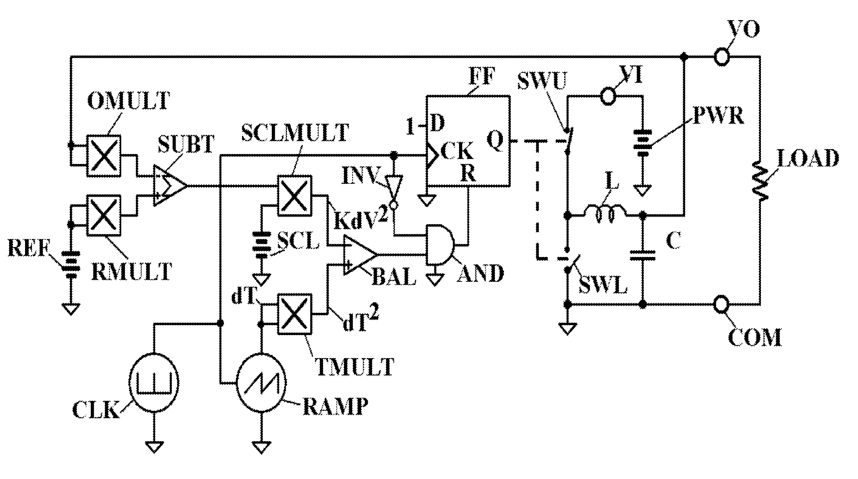
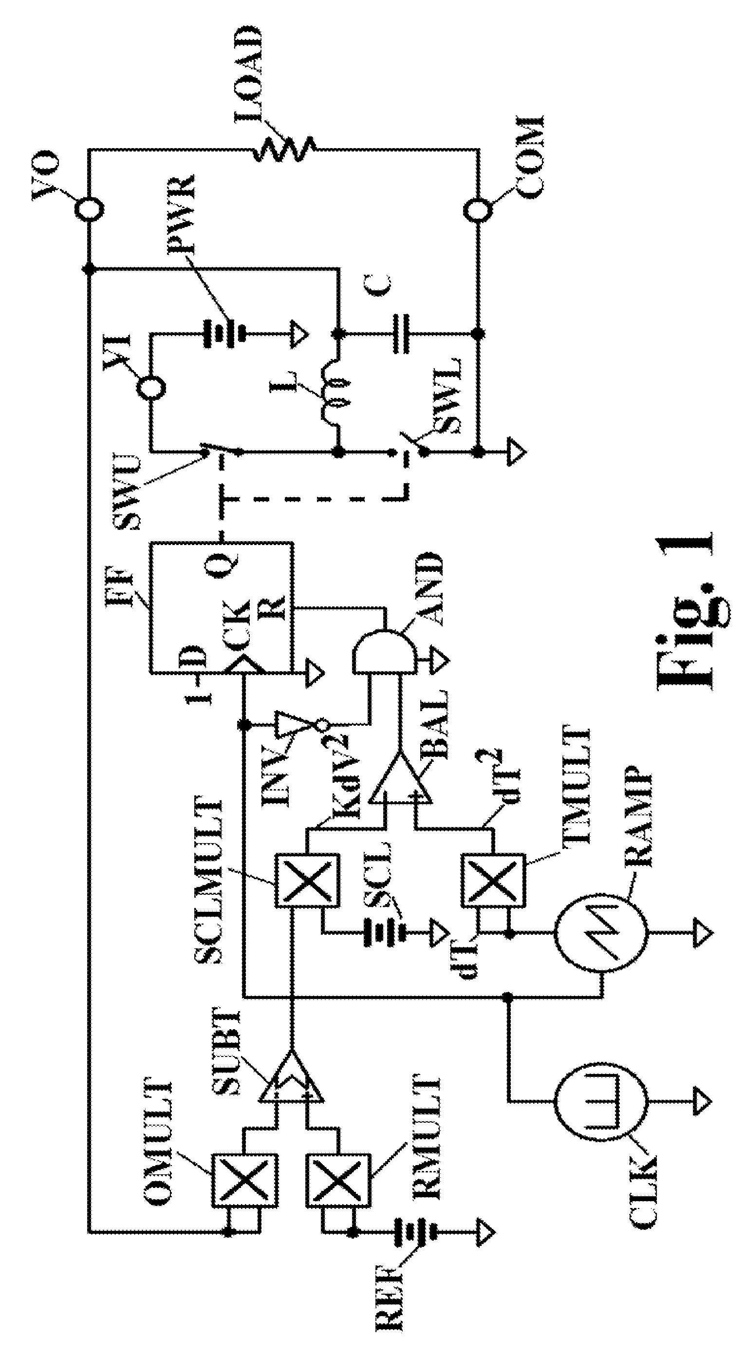
[0024]Referring first to FIG. 1, a conventional totem-pole switch comprises SWU and SWL, upper and lower switches respectively. Driven by D flip-flop FF, at some duty cycle between the voltage from power source PWR on terminal VI and the voltage on terminal COM, the totem pole switch presents some average voltage to inductive reactor L. Reactor L and filter capacitor C form an output filter to smooth the output voltage presented to load LOAD through terminal VO. Inverter INV and AND-gate AND prevent FF from being reset during the clock pulse from clock generator CLK. These circuit functions are well known in the prior art.

[0025]According to this invention, the voltage at VO is also applied to both inputs of multiplier OMULT, the output of which, representing the square of actual output voltage at VO, is applied to the negative input of SUBT. A voltage from source REF, proportional to desired output voltage, is applied to both inputs of multiplier RMULT, the output of which, represen...


PUM


Abstract

A switched-mode buck power converter includes a power source, a first switch, an inductor for storing energy, a diode or second switch, and control circuitry. The inductor has a first end connected to an output node of the power converter, wherein the first switch is connected between the power source and a second end of the inductor. The diode or second switch is connected, at the second end of the inductor, between the first switch and a common node of the power converter. The control circuitry is configured to (i) characterize per cycle energy demand of the power converter, (ii) characterize per cycle inductive energy of the power converter, and (iii) compare the characterized energy demand to the characterized inductive energy to control the first switch.

Description

CROSS-REFERENCE TO RELATED APPLICATIONS[0001]The present application claims the benefit of U.S. Provisional Application No. 61 / 262,198 filed on Nov. 18, 2009, which is incorporated herein by reference.STATEMENT REGARDING FEDERALLY SPONSORED RESEARCH OR DEVELOPMENT[0002]The present invention was not developed with the use of any Federal Funds, but was developed independently by the inventors.BACKGROUND OF THE INVENTION[0003]Conventional buck converters are often controlled by comparison of inductive energize time with a voltage error term. Inductive energize time is often represented by a ramp signal. An auxiliary feedback loop based on current mode control is sometimes used in conjunction with voltage control to improve performance during continuous conduction mode (CCM). There are many prior art “slope compensation” techniques that modify the slope of the ramp signal to improve the stability of the converter control loop and / or to improve its dynamic response. Such techniques are e...

Claims


Application Information

Patent Timeline
Patent Type & Authority Patents(United States)
IPC IPC(8): G05F1/40G05F1/613
CPCH02M3/156
Inventor LAWSON, THOMAS E.MORONG, WILLIAM H.
Owner COGNIPOWER LLC
Why Eureka
Try Eureka