Carbon monoxide production method and application thereof

A production method and carbon monoxide technology, applied in the furnace, blast furnace details, furnace type and other directions, can solve the problems of unpredictable use of reducing agent, low separation and recovery rate, and low economical hydrogen reduction technology, so as to reduce the cost of reducing agent and reduce The effect of emissions

Pending Publication Date: 2022-07-08
POHANG IRON & STEEL CO LTD
View PDF7 Cites 0 Cited by
  • Summary
  • Abstract
  • Description
  • Claims
  • Application Information

AI Technical Summary

Problems solved by technology

However, the technology of selectively separating and recovering carbon monoxide and then blowing it back into the blast furnace has CO and N in the exhaust gas. 2 The problem of low separation and recovery rate, the low economic efficiency of the hydrogen reduction technology using hydrogen as the medium, and the unpredictable operation changes when using the reducing agent
In addition, in order to re-inject the separated CO gas and produced hydrogen into the blast furnace, there is a problem that the temperature must be increased to 1200°C or higher in consideration of the heat balance inside the blast furnace, so technology development is still required

Method used


Image

  • Carbon monoxide production method and application thereof
  • Carbon monoxide production method and application thereof
  • Carbon monoxide production method and application thereof

Examples


Embodiment 1

[0072] Example 1: Comparison based on carbon monoxide conversion

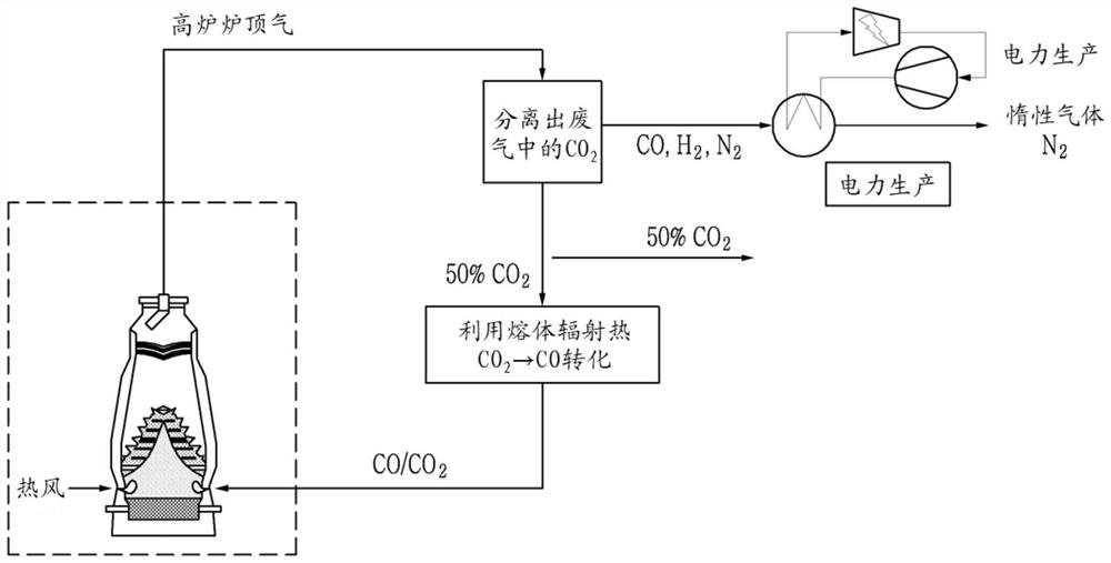
[0073]In the present invention, the carbon dioxide gas in the blast furnace waste gas is reformed into carbon monoxide, then re-injected through the blast furnace tuyere, and calculated by the thermal material balance equation to understand the blast furnace heat balance and carbon dioxide emission reduction effect. Table 1 shows the equilibrium and carbon dioxide emission reduction effects in the blast furnace caused by re-blowing carbon monoxide to the blast furnace tuyere according to the carbon monoxide gas conversion rate prepared according to an embodiment of the present invention for molten iron.

[0074] 【Table 1】

[0075]

[0076] *Base represents an existing blast furnace into which reformed carbon monoxide is not injected.

[0077] *t-p means ton-pig (ton pig iron).

[0078] [Formula 3] Pulverized coal blowing amount based on CO conversion rate (kg / ton pig iron)=-0.007*[CO conversion rate (%)] ...

Embodiment 2

[0081] Example 2: CO gas re-injection based on carbon monoxide conversion

[0082] The amount of CO gas that is re-blown into the blast furnace according to the carbon dioxide conversion rate is known through experiments.

[0083] The CO gas conversion rate was changed as shown in Table 2 below, and the amount of waste gas and molten iron production was kept constant.

[0084] The CO gas re-injection amount was calculated according to the following formula 1.

[0085] [Formula 1] Re-injection amount of CO gas (Nm 3 / min) = CO2 gas content in exhaust gas (Nm 3 / ton) × molten iron production (ton / day) × CO2 gas ratio (50%) × CO gas conversion rate (%) × (1 day / 1440 minutes)

[0086] 【Table 2】

[0087]

[0088]

[0089] From the results shown in the above table, it can be seen that when the CO gas re-injection amount is greater than 1270Nm 3 At the time of / min, the amount of carbon dioxide blown back into the blast furnace is increased, and therefore, the amount of...

Embodiment 3

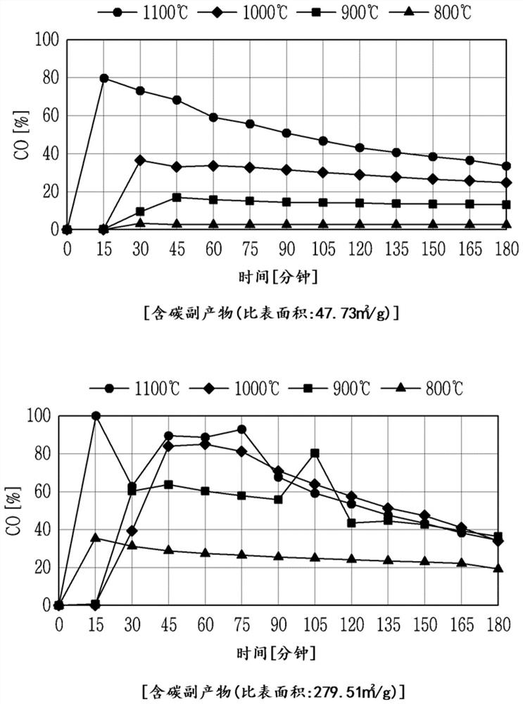
[0090] Example 3: Comparison of specific surface areas of carbon-containing by-products

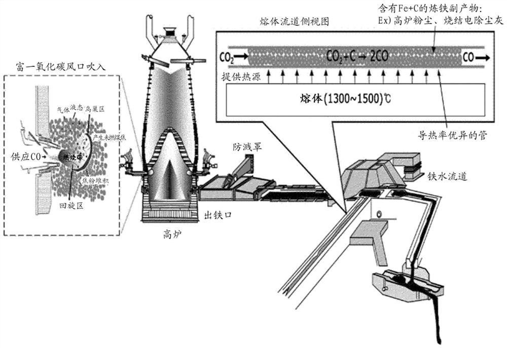
[0091] In order to realize the production of carbon monoxide in a carbon dioxide reformer using radiant heat in the flow channel, carbon dioxide was blown into reaction tubes filled with carbon-containing by-products with different specific surface areas as shown in Table 3, respectively, and the conversion rate according to the temperature was measured. , and the results are shown in Table 3. It can be seen that as the reaction temperature becomes higher and higher due to the radiant heat of the flow channel, the conversion of carbon monoxide increases, and at the same reaction temperature, a 20% higher conversion of carbon-containing by-products with good specific surface area is observed (see image 3 ). However, re-injecting carbon monoxide with a conversion rate of 85% means that the total input gas blown into the blast furnace will decrease, so it is necessary to increase the oxyge...


PUM

PropertyMeasurementUnit
specific surface areaaaaaaaaaaa

Abstract

The invention relates to a carbon dioxide reforming device, a molten iron production system and a molten iron production method. The carbon dioxide reforming device is filled with a mixture of a carbon-containing by-product and an iron-containing by-product at a mixing ratio of the carbon-containing by-product to the iron-containing by-product, the iron-containing by-product being 0 to 50 wt% based on 100 wt% of the carbon-containing by-product, and the carbon dioxide reforming device is used for reforming carbon dioxide into carbon monoxide. The molten iron production system recycles carbon dioxide in blast furnace waste gas through the carbon dioxide reforming device.

Description

technical field [0001] The present disclosure relates to a method for producing carbon monoxide. More specifically, the present disclosure relates to a carbon monoxide production method that converts carbon dioxide to carbon monoxide and utilizes the carbon monoxide to reduce carbon dioxide emissions. Background technique [0002] The reduction process in the steel industry is a process in which the carbon in the coke reacts with iron ore at high temperatures in a blast furnace called a blast furnace to obtain liquid iron. The problem with the current iron and steelmaking process is that the use of carbon-based reducing agents such as coal in the reduction process will inevitably generate a large amount of carbon dioxide (CO 2 ). However, as global CO2 emission regulation pressure intensifies, the steel industry is increasingly interested in environmentally friendly processes in terms of environmental, energy and cost competitiveness. Efforts to reduce carbon dioxide emis...

Claims


Application Information

Patent Timeline
Patent Type & Authority Applications(China)
IPC IPC(8): C21B5/06
CPCC21B5/06C21B7/002C21B7/007C21B2100/284C21B2100/282C21B2100/62C21B2100/80Y02P10/122
Inventor 李承纹梁永哲
Owner POHANG IRON & STEEL CO LTD
Why Eureka
Try Eureka