Apparatus for dental surface shape and shade imaging

a technology of surface shape and shade, applied in the field of diagnostic imaging, can solve the problems of difficult registration or correlation of shade information to shape information, human error in color shade decisions in particular, and preventing effective use of fringe projection imaging of teeth, etc., to achieve the effect of improving the imaging of tooth surfaces, obtaining tooth shade information, and reducing costs

Inactive Publication Date: 2013-10-29
CARESTREAM DENTAL LLC
View PDF21 Cites 104 Cited by
  • Summary
  • Abstract
  • Description
  • Claims
  • Application Information

AI Technical Summary

Benefits of technology

[0015]An advantage offered by the apparatus and method of the present invention relates to improved imaging of tooth surfaces and obtaining tooth shade information at lower cost over conventional contour imaging methods. Unlike conventional methods, no powder or other opaque substance must be applied to the tooth as a preparatory step for contour imaging.

Problems solved by technology

This makes it difficult to register or correlate the shade information to the shape information.
Color shade decisions in particular are subject to human error and the overall accuracy often depends on the relative experience of the practitioner.
However, a number of technical obstacles have prevented effective use of fringe projection imaging of the tooth.
One challenge with dental surface imaging relates to tooth translucency.
Translucent or semi-translucent materials in general are known to be particularly troublesome for fringe projection imaging.
Subsurface scattering in translucent structures can reduce the overall signal-to-noise (S / N) ratio and shift the light intensity, causing inaccurate height data.
Another challenge relates to high levels of reflection for various tooth surfaces.
In fringe projection imaging overall, contrast is typically poor, with noise as a significant factor.
From an optics perspective, the structure of the tooth itself presents a number of additional challenges for fringe projection imaging.
Moreover, reflection from opaque features beneath the tooth surface can also occur, adding noise that degrades the sensed signal and thus further complicating the task of tooth surface analysis.
However, there are drawbacks to this type of approach.
The step of applying a coating powder or liquid adds cost and time to the tooth contour imaging process.
Because the thickness of the coating layer itself has a given thickness and is often non-uniform over the entire tooth surface, measurement errors readily result.
Further, the applied coating, while it facilitates contour imaging, can tend to mask other problems with the tooth and can thus reduce the overall amount of information that can be obtained.
Even where a coating or other type of surface conditioning of the tooth is used, it can still be difficult to provide sufficient amounts of light onto, and to sense light reflected back from, all of the tooth surfaces.
Different surfaces of the tooth can be oriented at 90 degrees relative to each other, making it difficult to direct enough light for accurately imaging all parts of the tooth, whether or not a coating is applied.
Thus, color shade information and surface contour information must be obtained separately, making it difficult to register the shade and shape information to each other.
While confocal imaging methods may have some advantages, there are disadvantages to using such methods.
When this processing is done externally at a connected host computer or processor, there can be considerable overhead due to the needed volume of data transferred to the host computer or processor for confocal devices.
There are also disadvantages related to optical components and design.
Confocal imaging requires telecentric illumination and imaging paths, thus limiting the field of view of the imaging device.

Method used


Image

  • Apparatus for dental surface shape and shade imaging
  • Apparatus for dental surface shape and shade imaging
  • Apparatus for dental surface shape and shade imaging

Examples


Embodiment Construction

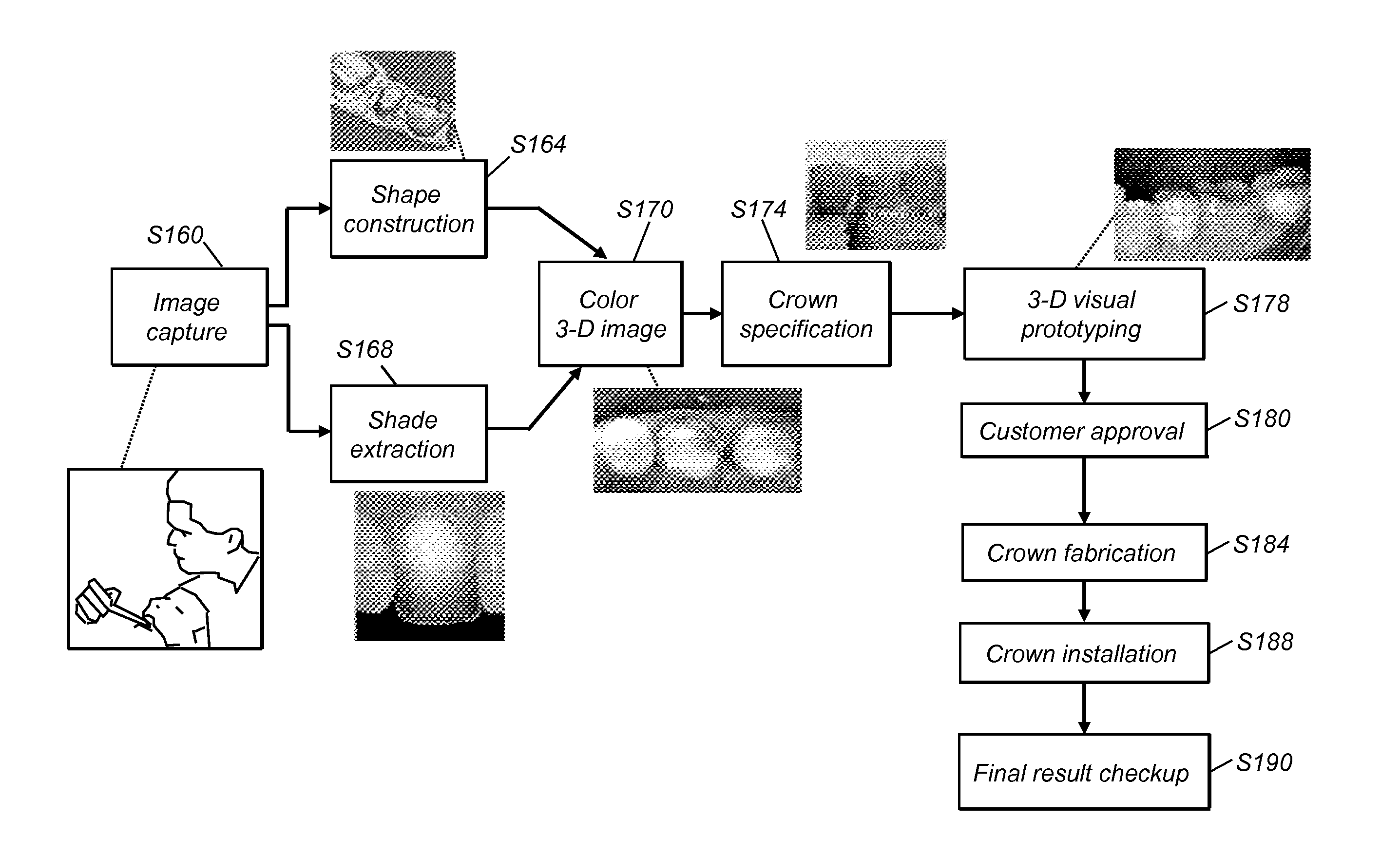
[0035]Reference is made to U.S. patent application Ser. No. 12 / 424,562 entitled “Dental Surface Imaging Using Polarized Fringe Projection” (Liang), filed 16 Apr. 2009, and commonly assigned.

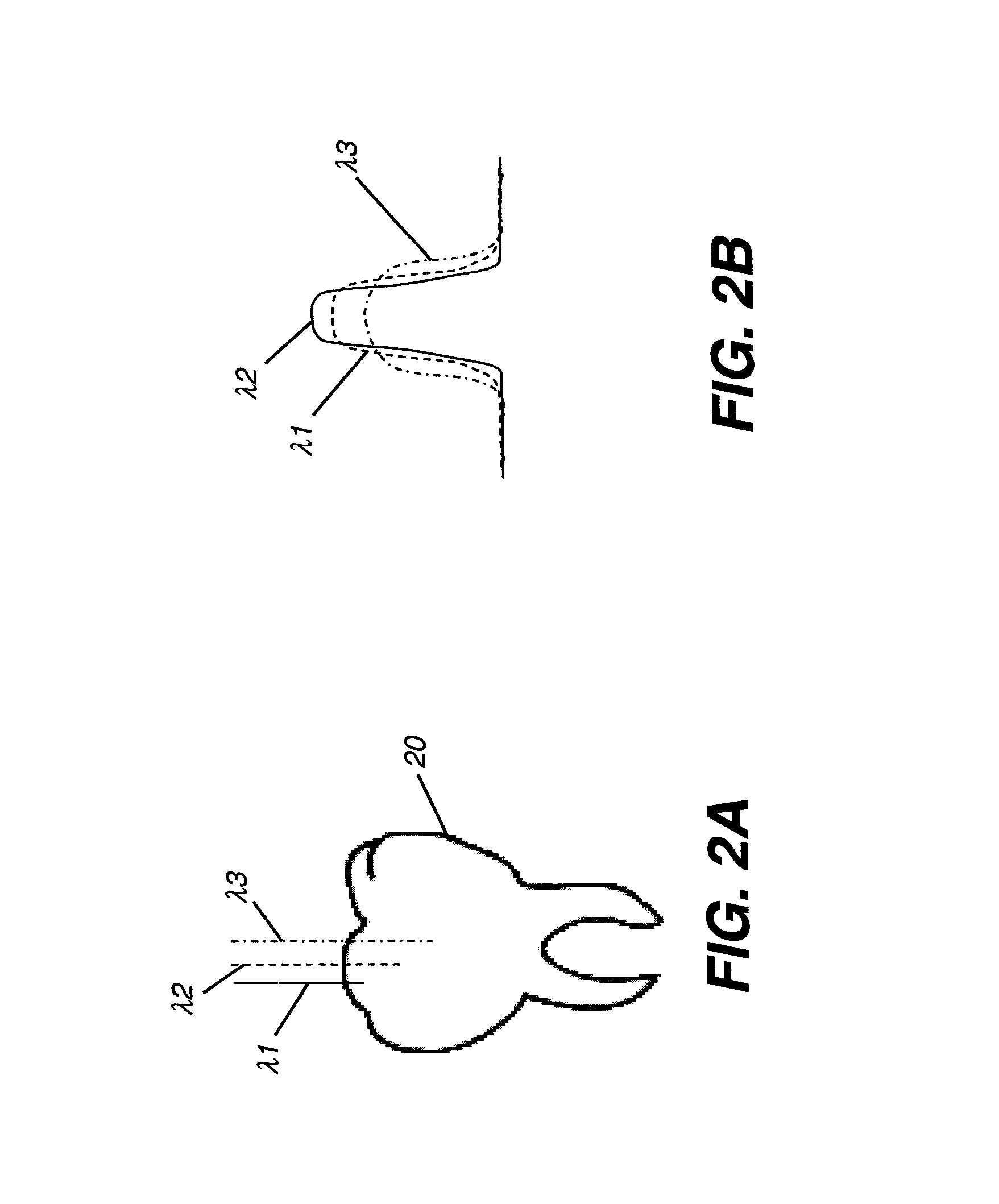
[0036]Figures provided herein are given in order to illustrate key principles of operation and component relationships along their respective optical paths according to the present invention and are not drawn with intent to show actual size or scale. Some exaggeration may be necessary in order to emphasize basic structural relationships or principles of operation. Some conventional components that would be needed for implementation of the described embodiments, such as support components used for providing power, for packaging, and for mounting and protecting system optics, for example, are not shown in the drawings in order to simplify description of the invention itself. In the drawings and text that follow, like components are designated with like reference numerals, and similar descriptions c...


PUM


Abstract

An intra-oral imaging apparatus having an illumination field generator that forms an illumination beam having a contour fringe projection pattern when receiving light from a first light source and having a substantially uniform illumination field when receiving light from a second light source. A polarizer in the path of the illumination beam has a first polarization transmission axis. A projection lens directs the polarized illumination beam toward a tooth surface and an imaging lens directs at least a portion of the light from the tooth surface along a detection path. A polarization-selective element disposed along the detection path has a second polarization transmission axis. At least one detector obtains image data from the light provided through the polarization-selective element. A control logic processor responds to programmed instructions for alternately energizing the first and second light sources in a sequence and obtaining both contour fringe projection data and color image data.

Description

FIELD OF THE INVENTION[0001]The invention generally relates to the field of diagnostic imaging and more particularly relates to an apparatus and method for combined three-dimensional shape and color shade imaging of the surface of teeth and other structures.BACKGROUND OF THE INVENTION[0002]Accurately modeling both the shape and color shade of a tooth are important functions for providing restorative dentistry and related services. Conventionally, the functions of determining tooth contour and matching tooth shade have been performed as separate operations. This makes it difficult to register or correlate the shade information to the shape information. Color shade decisions in particular are subject to human error and the overall accuracy often depends on the relative experience of the practitioner.[0003]With the advent of digital imaging technologies, a number of tools have been made available for obtaining either surface contour data or color shade information from the tooth. One t...

Claims


Application Information

Patent Timeline
Patent Type & Authority Patents(United States)
IPC IPC(8): G01B11/24
CPCA61B1/00009A61B1/24A61B5/1077A61B5/1079A61B5/4547G01B11/25G01B11/2527A61B6/14A61B6/145A61C13/34A61C19/04
Inventor LIANG, RONGGUANG
Owner CARESTREAM DENTAL LLC
Why Eureka
Try Eureka