Display device

a display device and display circuit technology, applied in the field of display devices, can solve the problems of circuit damage, electronic paper bending may be limited by the driver circuit, and difficulty in carrying

Active Publication Date: 2013-11-05
SEMICON ENERGY LAB CO LTD
View PDF20 Cites 62 Cited by
  • Summary
  • Abstract
  • Description
  • Claims
  • Application Information

AI Technical Summary

Benefits of technology

[0008]An object of one embodiment of the disclosed invention is to provide a display device including a flexible panel that can be handled without seriously damaging a driver circuit or a connecting portion between circuits.
[0009]One embodiment of the disclosed invention is a display device including a bent portion obtained by bending an element substrate. A circuit for driving the display device is provided in the bent portion and a wiring extends from the circuit, whereby the strength of a portion including the circuit for driving the display device is increased and failure of the circuit is reduced. Furthermore, the element substrate is bent in a connecting portion between an external terminal electrode and an external connecting wiring (FPC) so that the edge of the substrate provided with the external terminal electrode fits the external connecting wiring, whereby the strength of the connecting portion is increased.
[0021]According to one embodiment of the disclosed invention, it is possible to provide a robust display device having a driver circuit or a connecting portion between circuits which is unlikely to be damaged.

Problems solved by technology

However, the display device incorporated in a personal computer or the like is largely different from paper media like newspapers and magazines, and has a problem of inconvenience such as difficulty in carrying.
In the case where an element such as a transistor is used in a display portion of the flexible electronic paper, it is necessary to provide a circuit for driving the transistor, and in that case, the circuit may be damaged when the electronic paper is bent (curved).
Also in the case where an element such as a transistor is used in a display portion of the flexible electronic paper, the bending of the electronic paper may be limited by the driver circuit.

Method used


Image

  • Display device
  • Display device
  • Display device

Examples


embodiment 1

[0041]A structure disclosed in this embodiment will be schematically described with reference to FIGS. 1A and 1B and FIGS. 5A to 5C.

[0042]A display device shown in this embodiment includes an element substrate having flexibility, a display portion provided over the element substrate, a supporting portion which holds and fixes a side of the element substrate having flexibility (in a manner that prevents its movement), and a bent portion obtained by bending the element substrate. The bent portion includes a driver circuit for driving the display portion, such as a scan line driver circuit. The supporting portion includes, for example, a signal line driver circuit that outputs a signal to a signal line.

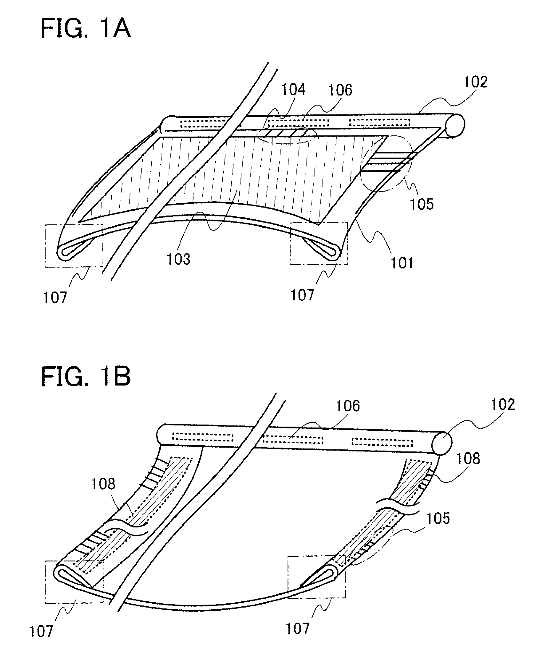
[0043]FIGS. 1A and 1B illustrate an example of the display device, which includes a supporting portion 102 provided on a side of an element substrate 101. The structure of the display device will be specifically described below with reference to FIGS. 1A and 1B. Note that FIG. 1A is a pe...

embodiment 2

[0055]A structure different from that shown in Embodiment 1 will be described with reference to FIG. 2, FIGS. 3A to 3C, and FIGS. 4A to 4C.

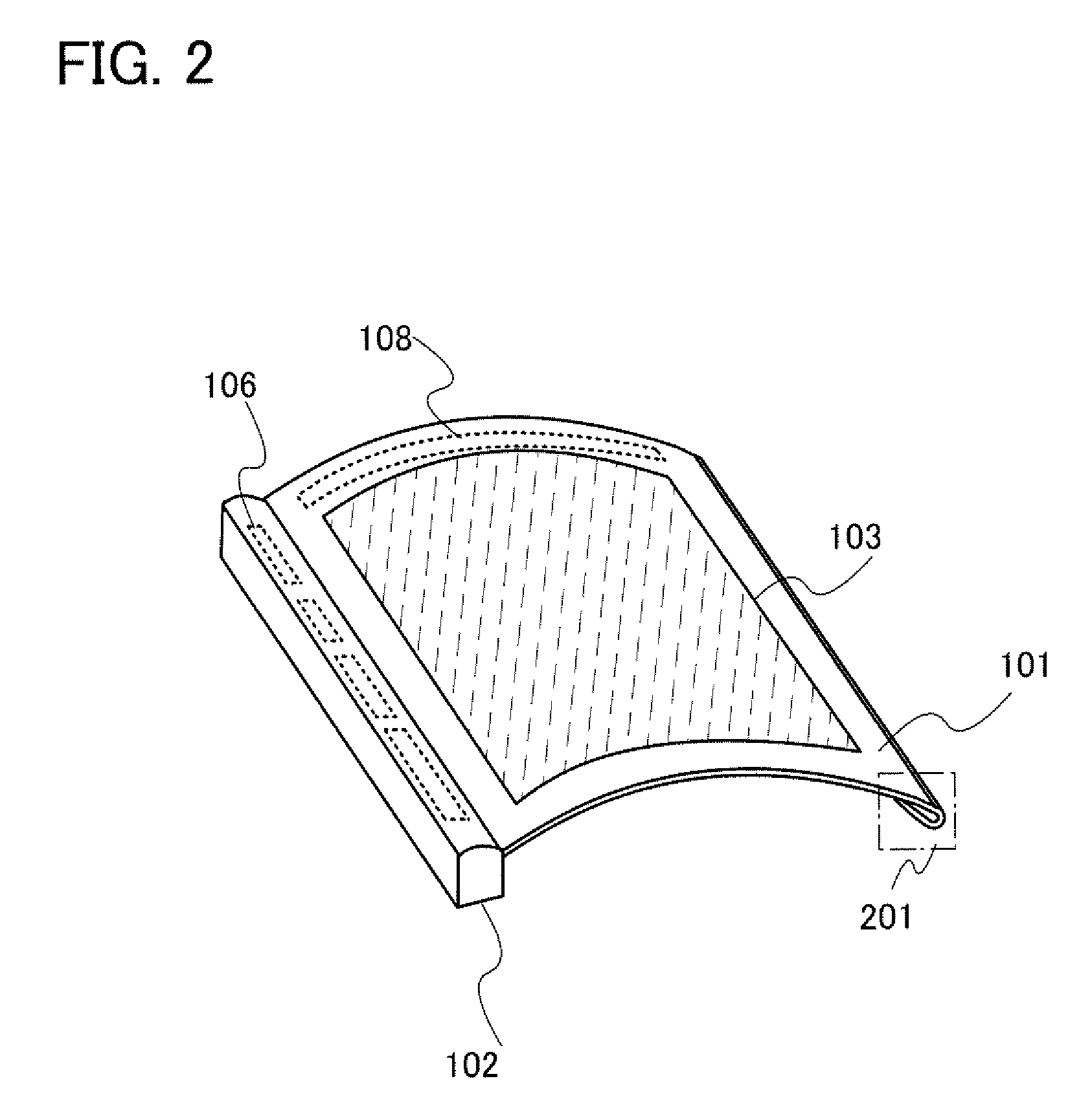
[0056]In a display device of this embodiment, as illustrated in FIG. 2, a bent portion 201 is provided on a side opposite to the supporting portion 102, namely, in a direction parallel to the long axis of the supporting portion 102. In addition, as in the above embodiment, a curved portion can be formed by bending the periphery of the element substrate having flexibility, which makes it possible to reduce injury of the user caused by a slip of a finger or the like on the edge of the display device.

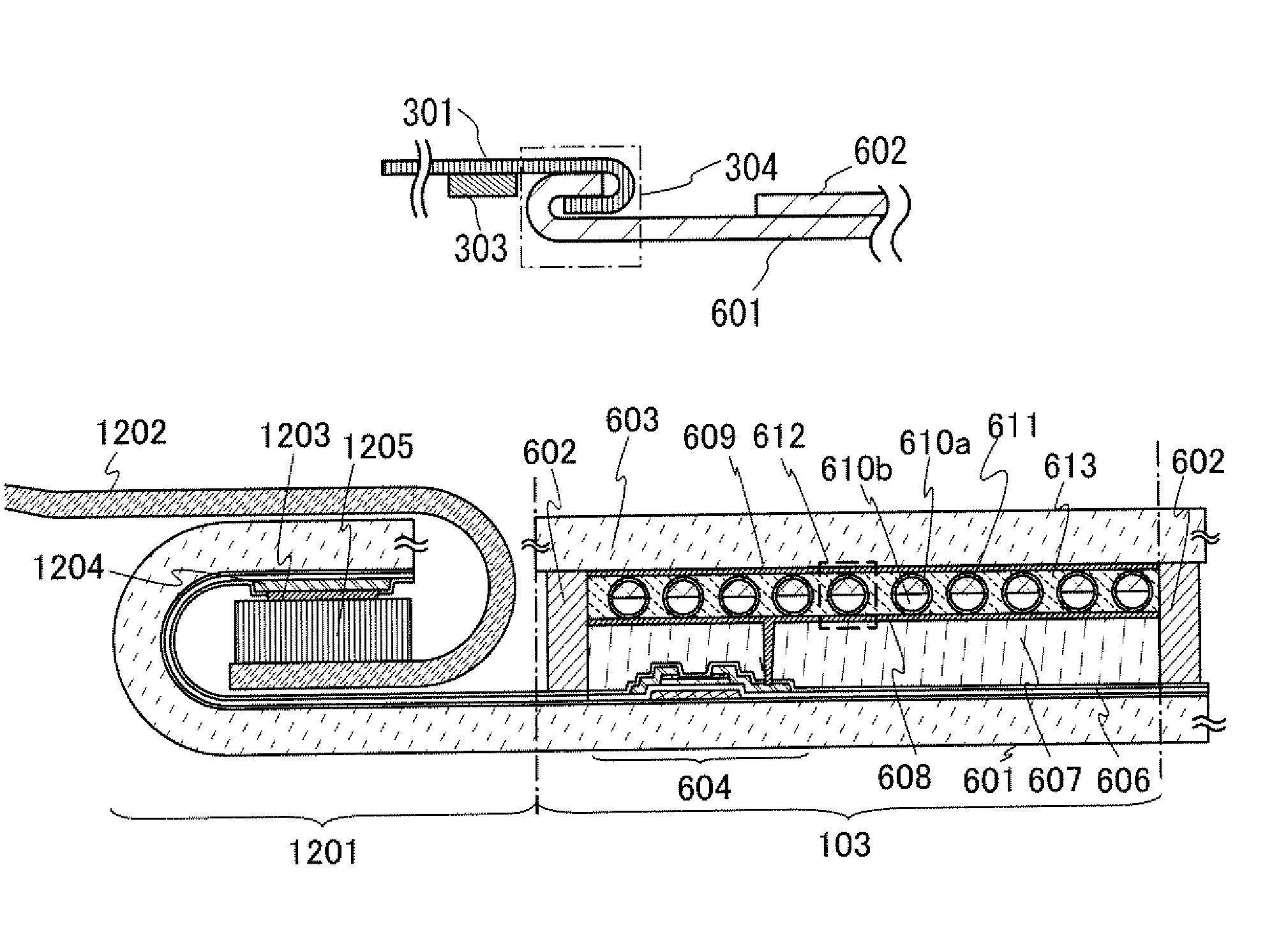
[0057]FIG. 3A is a top view of the display device, FIG. 3B is a cross-sectional view along line A-B of FIG. 3A, and FIG. 3C is an enlarged view of the cross section of FIG. 3B.

[0058]In the display device illustrated in FIG. 3A, a housing having a cavity is used for the supporting portion 102 and a signal line driver circuit is provided inside the housin...

embodiment 3

[0065]In this embodiment, an example of the structure of the display device will be described with reference to perspective views and cross-sectional views.

[0066]As the display device, electronic paper using an electrophoretic element as a display element, a light-emitting display device (an electroluminescence (EL) panel), a liquid crystal display device, and the like can be employed. The display device is a panel in which a display element is sealed. The panel includes a terminal electrode to which a signal is externally supplied (an external terminal electrode), and a connector, e.g., an external connecting wiring such as a flexible printed circuit (FPC), a tape automated bonding (TAB) tape, or a tape carrier package (TCP), is attached to the terminal electrode, whereby the panel is electrically connected to an external circuit including a driver circuit. An IC including the driver circuit may be directly mounted on the display device by chip on glass (COG).

[0067]An embodiment of...


PUM

PropertyMeasurementUnit
diameteraaaaaaaaaa
wavenumberaaaaaaaaaa
frequencyaaaaaaaaaa

Abstract

To provide a display device including a flexible panel that can be handled without seriously damaging a driver circuit or a connecting portion between circuits. The display device includes a bent portion obtained by bending an element substrate. A circuit for driving the display device is provided in the bent portion and a wiring extends from the circuit, whereby the strength of a portion including the circuit for driving the display device is increased and failure of the circuit is reduced. Furthermore, the element substrate is bent in a connecting portion between an external terminal electrode and an external connecting wiring (FPC) so that the element substrate provided with the external terminal electrode fits the external connecting wiring, whereby the strength of the connecting portion is increased.

Description

BACKGROUND OF THE INVENTION[0001]1. Field of the Invention[0002]The present invention relates to a display device.[0003]2. Description of the Related Art[0004]In recent years, with the development of digitization techniques, text data and image data of newspapers, magazines, and the like have been provided as electronic data. This kind of electronic data is generally displayed on a display device incorporated in a personal computer or the like, so that the content of the data can be read.[0005]However, the display device incorporated in a personal computer or the like is largely different from paper media like newspapers and magazines, and has a problem of inconvenience such as difficulty in carrying.[0006]In order to solve the above problem due to a difference in convenience between electronic data and paper media, electronic paper having flexibility has been proposed (for example, see Patent Document 1). In the case where an element such as a transistor is used in a display portio...

Claims


Application Information

Patent Timeline
Patent Type & Authority Patents(United States)
IPC IPC(8): G09G5/00G02F1/167
CPCG02F1/133305G02F1/13454G06F1/1652H05K1/028H01L27/1218G02F1/167Y02E10/549G02B26/026G02F1/1368G09G5/003G09G2310/0202G09G2310/0267H01L23/562H05K5/0017
Inventor MIYAGUCHI, ATSUSHI
Owner SEMICON ENERGY LAB CO LTD
Why Eureka
Try Eureka