
Turbofan engine

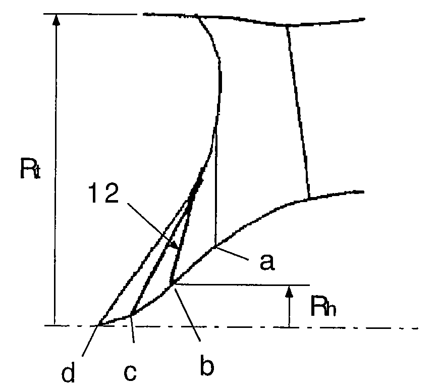
a technology of turbofan and engine body, which is applied in the direction of machines/engines, waterborne vessels, climate sustainability, etc., can solve the problems of increasing engine weight and engine weight, and achieve the effect of increasing the flow rate, increasing the hub-side pressure ratio, and increasing the flow ra

Active Publication Date: 2013-11-12
IHI CORP
View PDF29 Cites 7 Cited by
  • Summary
  • Abstract
  • Description
  • Claims
  • Application Information

AI Technical Summary

Benefits of technology

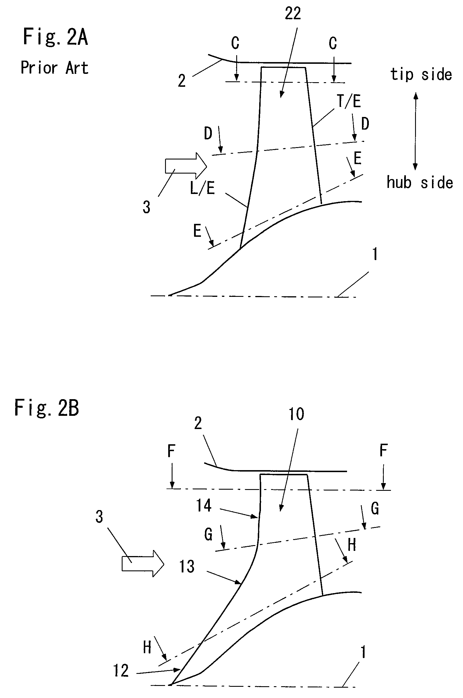
This configuration enables increased air flow rates and pressure ratios without enlarging the fan or casing diameters, reducing weight, fuel consumption, and noise levels while maintaining performance.

Problems solved by technology

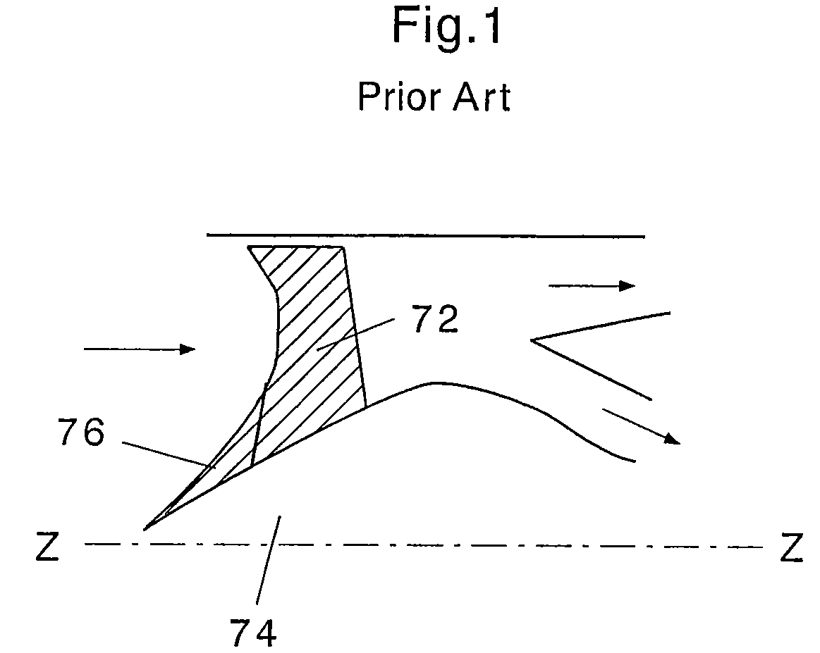
However, in the above-described turbofan engine, a problem arises in that a fan first-stage rotating blade (an up-front fan) and an inner diameter of a casing surrounding the fan first-stage rotating blade are enlarged by enlarging the bypass ratio, and a weight of the engine is increased.
As described above, in the above-described turbofan engine, a problem arises in that the fan first-stage rotating blade (an up-front fan) and an inner diameter of a casing surrounding the fan first-stage rotating blade are enlarged by enlarging the bypass ratio, and a weight of the engine is increased.

Method used


Image

  • Turbofan engine
  • Turbofan engine
  • Turbofan engine

Examples


first embodiment

[First Embodiment]

[0064]FIGS. 6A to 6C are diagrams showing an embodiment of the turbofan engine according to the invention. In these drawings, FIG. 6A shows a constant pressure ratio line, FIG. 6B shows a distribution of the pressure ratio in a span direction, and FIG. 6C shows a comparison with the conventional art. These are obtained by a simulation result (CFD calculation result) using a computer.

[0065]In FIG. 6A, a to j indicate the constant pressure ratio line from the leading edge part to the trailing edge part of the fan first-stage rotating blade according to the invention. From this drawing, it is understood that the pressure efficiently increases on the hub side of the fan first-stage rotating blade 10.

[0066]In FIG. 6B, a to j correspond to those of FIG. 6A. From this drawing, it is understood that the pressure ratio on the hub side of the fan first-stage rotating blade 10 is larger than those on the tip side and the mid span.

[0067]As shown in FIG. 6C, the CFD calculation...


PUM

PropertyMeasurementUnit
chord lengthaaaaaaaaaa
chord lengthsaaaaaaaaaa
outer-diameteraaaaaaaaaa

Abstract

A hub-side leading edge part of a fan first-stage rotating blade 10 for taking an air thereinto more extends in a forward direction of an engine than a tip-side leading edge part and a mid-span leading edge part. The hub side of the fan first-stage rotating blade 10 is integrally connected as one with the tip side and the mid span while having a longer chord length than those of the tip side and the mid span. A radius at a root of the hub-side leading edge part is set in a boss ratio of 0 to 0.4.

Description

[0001]This is a National Phase Application in the United States of International Patent Application No. PCT / JP2007 / 057744 filed Apr. 6, 25007, which claims priority of Japanese Paten Application No. 184207 / 2006 filed Jul. 4, 2006. The entire disclosures of the above patent applications are hereby incorporated by reference.BACKGROUND OF THE INVENTION[0002]1. Technical Field of the Invention[0003]The present invention relates to a turbofan engine.[0004]2. Description of Related Art[0005]A turbojet engine of an aircraft having a bypass flow in the downstream of a fan for taking an air thereinto is called as “turbofan engine”. A bypass ratio corresponds to a flow rate ratio (bypass flow / core flow) between an air flow (a core flow) flowing into a core engine (a compressor, a combustor, and a turbine) and a bypass flow bypassing them. There is obtained an effect of reducing a flow speed of an exhaust jet and lowering a noise and a specific fuel consumption, in accordance with an increase ...

Claims


Application Information

Patent Timeline
Patent Type & Authority Patents(United States)
IPC IPC(8): B23K5/08
CPCF01D5/141F04D29/384Y02T50/671Y02T50/673Y02T50/60F04D29/324F05D2250/70
Inventor KODAMA, HIDEKAZUGOTO, SHINYAMIZUTA, IKUHISAMUROOKA, TAKESHI
Owner IHI CORP
Learn More