Automation devices, systems, architectures, and methods including controllable transfer switches

a technology of automatic devices and transfer switches, applied in the field of automatic systems, can solve the problems of not substantially broadening the market for home automation products, difficult implementation and maintenance of home automation systems, and high cost, and achieve the effects of improving performance, reducing labor intensity, and reducing labor intensity

Active Publication Date: 2013-11-12
AUTANI LLC
View PDF2 Cites 24 Cited by
  • Summary
  • Abstract
  • Description
  • Claims
  • Application Information

AI Technical Summary

Benefits of technology

The present invention is an automation controller that can manage the automation of a facility or workspace. It can control various devices and functions such as temperature, lighting, and access control. The controller can also monitor the status of peripheral devices and quickly respond to changes. It can also control the distribution of electricity to different circuits based on power loss or user preferences. The controller can detect the presence of people using electronic activity monitoring, which allows for quicker transition of areas from occupied to unoccupied. The automation controller can also coordinate different energy management activities within a facility to minimize energy cost and consumption.

Problems solved by technology

A major reason being that home automation systems tend to be difficult to implement and maintain and / or extremely expensive relative to the utility and benefits of the system.
Common criticisms of X10 are directed toward its reliability and robustness, as well as the level of user-friendliness.
Other PLC protocols have been developed to address the criticisms of X10, which have enhanced performance and user experience, but have not substantially broadened the market for these products.
The high-end of the residential market has typically been addressed by comprehensive and expensive stand-alone systems, which often require the use of professional services firms to install and possibly maintain the system.
In addition to the price of the comprehensive system, the cost and inconvenience associated with providing an infrastructure to support these systems in existing structures has further constrained the market.
Otherwise, these consumers are also generally limited to the use of programmable thermostats and motion controlled lighting.
As such, most energy consumers have little visibility into their energy consumption patterns.
The lack of visibility makes it difficult to modify or tailor consumption patterns to reduce the energy consumed or the cost of the energy being consumed.
Furthermore, participation in utility based conservation programs, such as demand-response programs, is typically limited to those residential and non-residential facilities that can operate with periodic interruptions of their air conditioning systems.

Method used


Image

  • Automation devices, systems, architectures, and methods including controllable transfer switches
  • Automation devices, systems, architectures, and methods including controllable transfer switches
  • Automation devices, systems, architectures, and methods including controllable transfer switches

Examples


Embodiment Construction

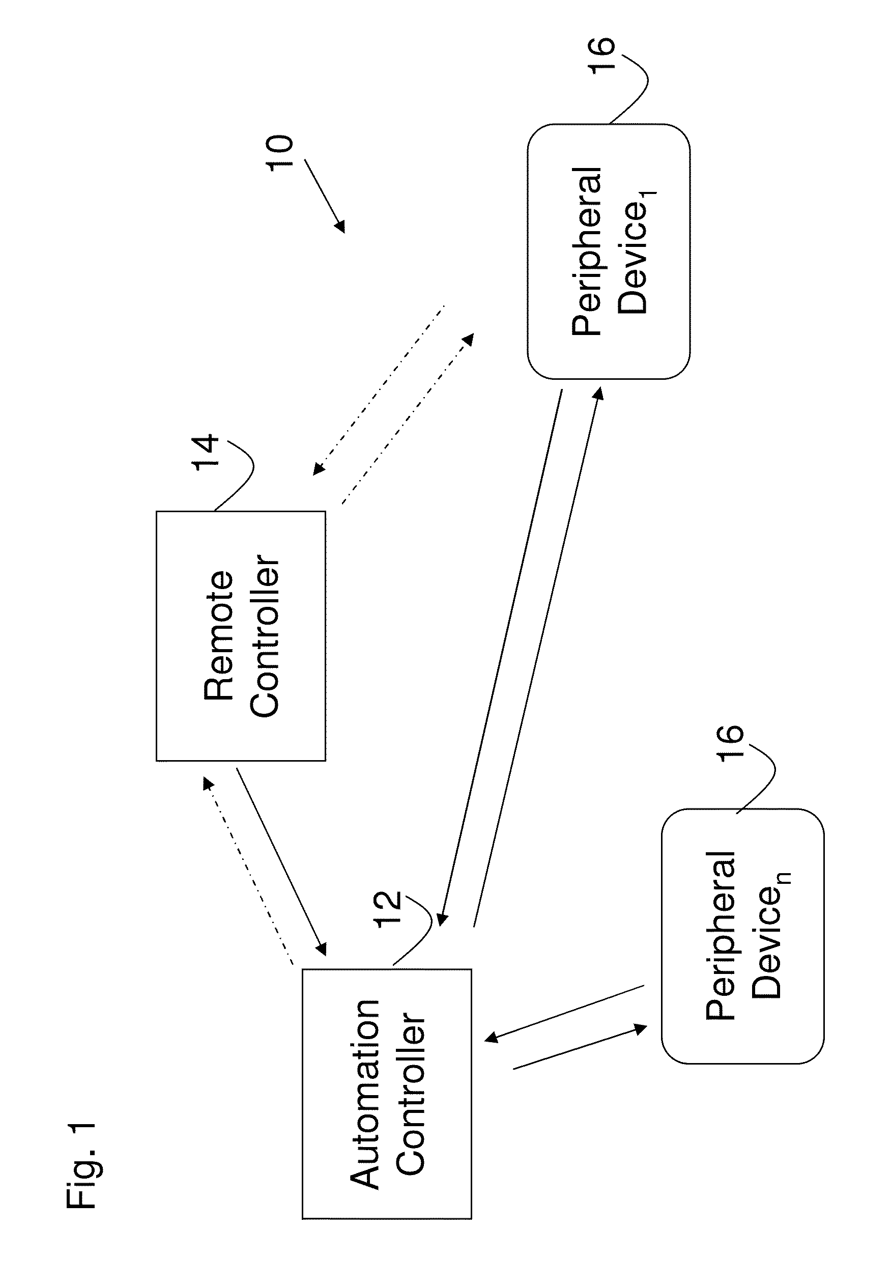
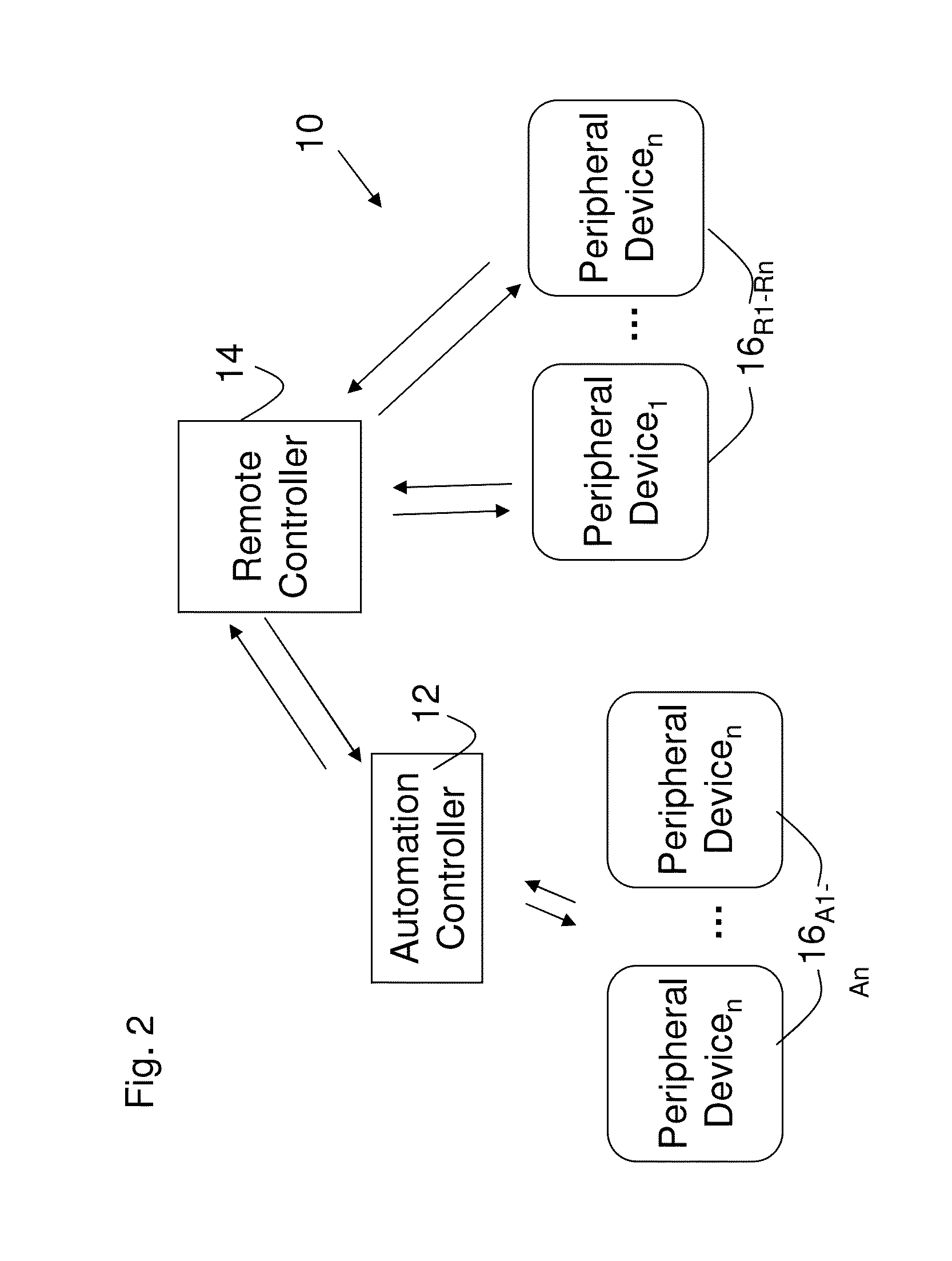
[0052]FIG. 1 depicts an automation system 10 embodiment of the present invention. The system 10 includes various components, such as an automation controller 12, a remote controller 14, and one or more peripheral devices 161-n. In this embodiment, the automation controller 12 has two way communications with the peripheral device 16 (as shown by the solid arrows). It also has at least one way communication with the remote controller 14, and, optionally two way communications with the remote controller 14 (as indicated by the dashed arrows). In addition, the remote controller 14 can have optional one or two way communications with one or more of the peripheral devices 161-n.

[0053]Communication between the automation controller 12 and the peripheral devices 16 can be wired and / or wireless depending upon the particular implementation. Wired communication can make use of the power lines, local area networks, or direct links between communication ports, such as USB, RS-232 and 485, etc. W...


PUM


Abstract

An automation system including a plurality of peripheral devices, each configured to perform at least one function relating to energy consumption in a facility and an automation controller in communication with the plurality of peripheral devices and providing for the control of the performance of the function by each device, wherein the system includes a configurable transfer switch that enables the system to control the flow and / or source of electricity provided to circuits in a facility.

Description

CROSS-REFERENCE TO RELATED APPLICATIONS[0001]This application claims the benefit of U.S. Provisional Patent Application No. 61 / 254,228 filed Oct. 23, 2009, which is incorporated herein by reference.STATEMENT REGARDING FEDERALLY-SPONSORED RESEARCH AND DEVELOPMENT[0002]Not Applicable.FIELD OF THE INVENTION[0003]The present invention is directed generally to automation systems and, more specifically, to automation systems to monitor and control conditions in and / or around buildings and the operation of energy systems.BACKGROUND OF THE INVENTION[0004]Automation of the work and leisure environment has been a concept that has been long pursued. Despite the continued pursuit, widespread automation, particularly in the home, has not gone much beyond the use of timers, programmable thermostats, and universal remote controls for audio and video equipment.[0005]In the home, higher levels of automation have been left to the domain of the hobbyist and high net worth individuals. A major reason b...

Claims


Application Information

Patent Timeline
Patent Type & Authority Patents(United States)
IPC IPC(8): H02J9/00
CPCH02J9/00H02J13/0006H02J3/14H02J2310/12H02J13/00004Y04S20/222Y02B70/3225H02J13/00022H02J13/00036
Inventor CLAYTON, RANDYMARTIN, HENRY
Owner AUTANI LLC
Why Eureka
Try Eureka