Shock absorber

a technology of shock absorber and shock absorber, which is applied in the direction of shock absorber, vibration damper, spring/damper, etc., can solve the problems of reducing productivity and increasing manufacturing cost, and achieves the effects of increasing coaxiality, high accuracy, and reducing productivity

Active Publication Date: 2013-11-19
HITACHI ASTEMO LTD
View PDF5 Cites 21 Cited by
  • Summary
  • Abstract
  • Description
  • Claims
  • Application Information

AI Technical Summary

Benefits of technology

[0005]It is, however, necessary in order to increase the coaxiality between the three members, i.e. the oil seal, the main disk valve and the valve member, to control the dimensions of each member with high accuracy, which causes a reduction in productivity and an increase in manufacturing cost. To obtain stable damping force characteristics during the generation of a low damping force, in particular, the sliding resistance needs to be reduced as much as possible, and it is necessary to ensure sealability while reducing the interference between the oil seal and the cylindrical portion of the valve member. Therefore, high dimensional accuracy and high coaxiality are required.
[0006]An object of the present invention is to provide a shock absorber configured to increase the slidability and sealability of an elastic seal member provided on the rear surface of a disk valve to form a back pressure chamber while reducing the coaxiality requirements for each part of a damping force generating mechanism.

Problems solved by technology

It is, however, necessary in order to increase the coaxiality between the three members, i.e. the oil seal, the main disk valve and the valve member, to control the dimensions of each member with high accuracy, which causes a reduction in productivity and an increase in manufacturing cost.

Method used


Image

  • Shock absorber
  • Shock absorber
  • Shock absorber

Examples


first embodiment

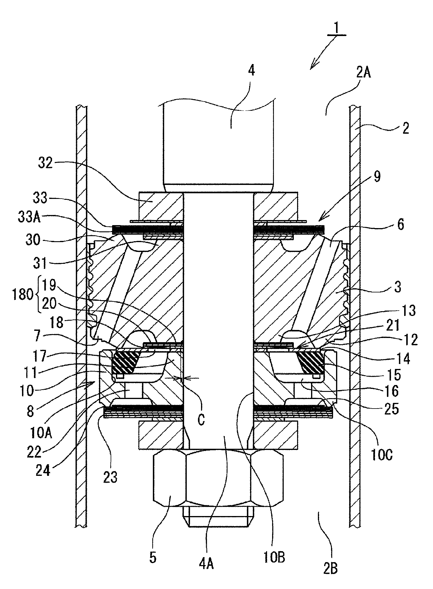
[0014]the present invention will be explained with reference to FIGS. 1 and 4. As shown in FIG. 1, a shock absorber 1 according to this embodiment is a single-tube hydraulic shock absorber attached to a suspension system of an automobile or other vehicle. A piston 3 is slidably fitted in a cylinder 2 (only a part of a side wall thereof is shown) having a hydraulic oil sealed therein as a hydraulic fluid. The piston 3 divides the interior of the cylinder 2 into two chambers, i.e. a cylinder upper chamber 2A and a cylinder lower chamber 2B. The piston 3 is connected to a shaft portion 4A at one end of a piston rod 4 by a nut 5. The other end of the piston rod 4 extends to the outside of the cylinder 2 through a rod guide (not shown) and an oil seal (not shown) that are fitted to the upper end of the cylinder 2. The cylinder lower chamber 2B is connected to a reservoir (not shown) through a base valve (not shown) having a proper flow resistance. The reservoir has the hydraulic oil and ...

second embodiment

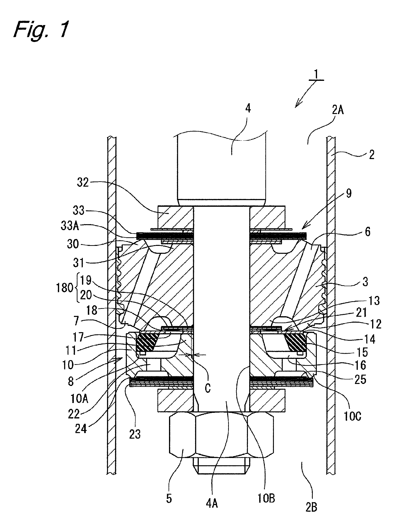
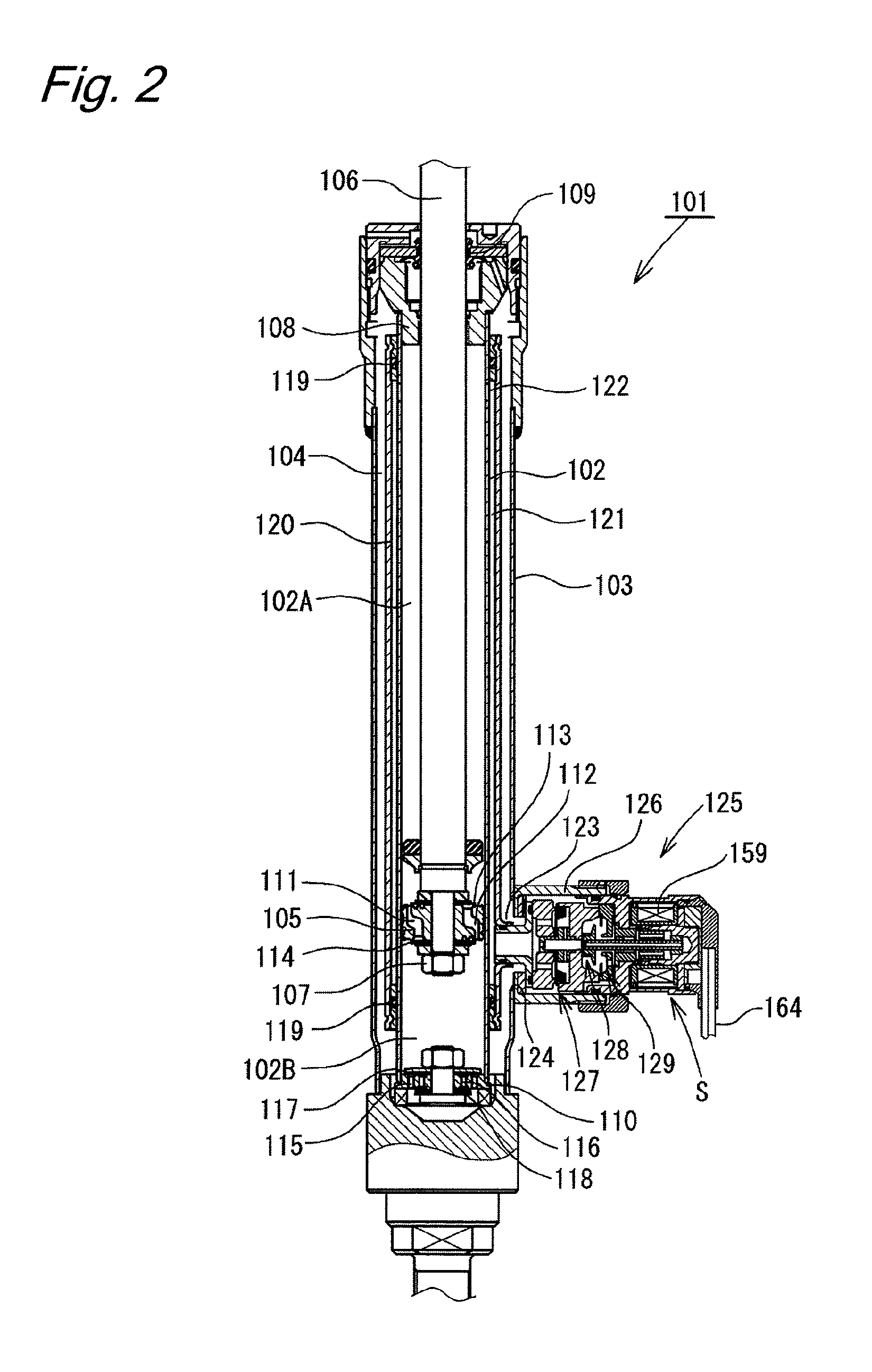
[0044]Next, the present invention will be explained with reference to FIGS. 2, 3 and 5.

[0045]As shown in FIG. 2, a shock absorber 101 according to this embodiment has a dual-tube structure comprising a cylinder 102 and an outer tube 103 provided outside the cylinder 102. A reservoir 104 is formed between the cylinder 102 and the outer tube 103. A piston 105 is slidably fitted in the cylinder 102. The piston 105 divides the interior of the cylinder 102 into two chambers, i.e. a cylinder upper chamber 102A and a cylinder lower chamber 102B. The piston 105 is connected to one end of a piston rod 106 by a nut 107. The other end portion of the piston rod 106 extends through the cylinder upper chamber 102A and further through a rod guide 108 and an oil seal 109, which are fitted to the upper end portion of the double-tube structure comprising the cylinder 102 and the outer tube 103, and projects to the outside of the cylinder 102. A base valve 110 is provided in the lower end portion of t...


PUM


Abstract

A piston connected to a piston rod is fitted in a cylinder having a hydraulic oil sealed therein. Flows of hydraulic oil induced by sliding movement of the piston are controlled by extension and compression damping force generating mechanisms and to generate damping force. In the extension damping force generating mechanism, the valve-opening pressure of a disk valve is controlled by the pressure in a back pressure chamber. An elastic seal member fixed to the disk valve is brought into sliding contact with an inner peripheral surface of a cylindrical portion of a valve member to seal the back pressure chamber. The disk valve is self-aligned by fitting between the elastic seal member and the inner peripheral surface of the valve member and secured by being axially clamped at an inner peripheral portion thereof in a state where a clearance is formed between the inner peripheral portion of the disk valve and a shaft portion of the piston rod, thereby reducing the requirements for coaxiality.

Description

BACKGROUND OF THE INVENTION[0001]The present invention relates to shock absorbers generating a damping force by utilizing the fluid pressure.[0002]Shock absorbers attached to suspension systems of automobiles or other vehicles generally have the following structure. A piston connected to a piston rod is slidably fitted in a cylinder having a fluid sealed therein. A stroke of the piston rod causes sliding movement of the piston in the cylinder, which, in turn, induces a flow of fluid. The fluid flow is controlled by a damping force control mechanism comprising an orifice, a disk valve, etc., thereby generating a damping force.[0003]A hydraulic shock absorber disclosed in Japanese Patent Application Publication No. 2006-10069, for example, has a back pressure chamber (pilot chamber) formed at the back of a main disk valve constituting a damping force generating mechanism. A part of the fluid flow is introduced into the back pressure chamber, and the pressure in the back pressure chamb...

Claims


Application Information

Patent Timeline
Patent Type & Authority Patents(United States)
IPC IPC(8): F16F9/34
CPCF16F9/348F16F9/34
Inventor MURAKAMI, HIROSHI
Owner HITACHI ASTEMO LTD
Why Eureka
Try Eureka